


Other Parts Discussed in Thread: UCC28070
Tool/software:
Hi TI team,
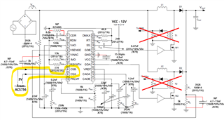
I'm designing a 6.6kW interleaved CCM Boost PFC using UCC28070APWR.
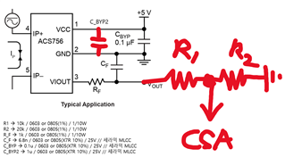
I’m using Allegro’s Hall-effect current sensor ACS756 to feeding its output (via resistor divider and LPF) into CSA and CSB pins for the current loop.
The setup is as follows:
- ACS756 has a 2.5V reference and 40mV/A sensitivity.
- For ±50A range → output spans 0.5V ~ 4.5V.
- I use a resistor divider (10k:20k) to scale the 4.5V max down to 3V max at CSA/CSB.
- There's also a 1k + (1uF, 0.1uF, 6.8nF) to suppress switching noise before reaching CSA.
Now, I understand that TI usually recommends using current sense resistors or CTs instead of Hall sensors due to potential bandwidth or stability concerns in analog loops.
But I would like to confirm:
1. Is there any known issue with using ACS756 (with proper filtering & scaling) in the current loop of UCC28070?
2. What loop stability considerations should I be aware of?
3. Do you recommend adjusting the PKLMT voltage if I'm using 3V as CSA/CSB peak?
I’m attaching a schematic snippet for reference (see below). Please let me know if this approach is acceptable or risky in any specific way.
Thanks in advance.
------------------------
Ki Young
