This thread has been locked.

If you have a related question, please click the "Ask a related question" button in the top right corner. The newly created question will be automatically linked to this question.

BQ28Z620: BQ28Z620DRZR: Cannot Keep CHG & DSG FETs enabled

Part Number: BQ28Z620
Other Parts Discussed in Thread: BQSTUDIO

Tool/software:

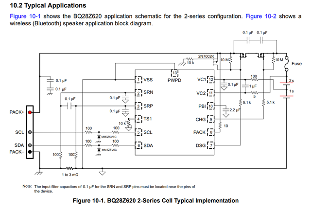
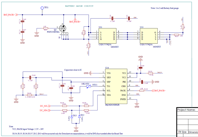
We are using BQ28Z620DRZR Gauge IC in our design for 3.6V single Li-Ion cell input.

1) When I am connecting single battery Li-Ion Cell 3.6V to the IC BQ28Z620DRZR VC1, VC2 pins, the CHG FET is ON, but DSG FET is OFF and voltage is not flowing to PACK input side, so in this case voltage is not flowing to loads such as like MCU, and other loads, etc.

But When I am connecting 3.6V to the PACK input side, both CHG FET & DSG FETs are ON. But in real-time not possible to connect like this, In this case how can we ON both CHG FET & DSG FETs through ICs VC1, VC2 single cell input voltage?

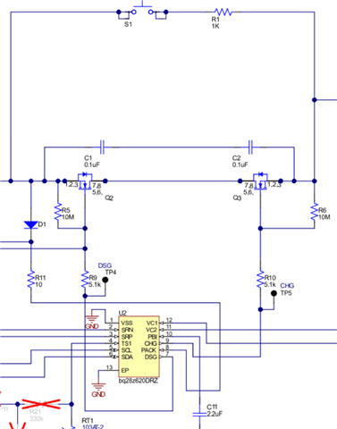
attached circuit for reference

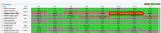
2) When we are using BQStudio for single battery cell calibration the INIT BIT is always ON. we need your input for how can we modify the INIT bit to LOW.

Any help is greatly appreciated.

  • Hello, 

    From the screenshot you have provided, it looks like the DSG FET is turned on. The key here is that you have FET_EN == 1 which is good as this means that the gauge is controlling the functionality of the FETs. Otherwise if FET_EN == 0 then you would have to manually control the DSG and CHG FETs through the CHG_FET_TOGGLE and DSG_FET_TOGGLE commands. Regarding your second question, please refresh the Registers page to update the registers page. It is likely that you have just not refreshed the Registers page and this is why you are not seeing the INIT bit change. 

    Regards, 

    Jonny. 

  • Hi, thanks for the reply.

    The DSG FET is ON when I apply voltage to the PACK input side through an any external power supply connection. However, in the final product, we don't have any external power to apply to the PACK input side. We only have a 3.6V Li-Ion single battery cell, which is connected to the IC's VC1 and VC2 pins. In this case, the CHG FET is turning ON, but the DSG FET is not turning ON, and the cell voltage is not flowing to the PACK side. This is the issue we are currently struggling with.

    Regards,

    Thangapandi.

  • Hello, 

    Can you please provide me with your .gg file as well as a BQStudio log file that shows this behavior? 

    Regards, 

    Jonny. 

  • BQ28Z620.zip

    Here I have attached the BQStudio .gg and .log file, please check this ZIP file.

  • Hi,

    Attached the above BQStudio ZIP file tested under the following conditions:

    1. Connected a 3.6V Li-Ion single cell to the IC's VC1 and VC2 pins.
    2. Once powered, the CHG FET conducts well, but the DSG FET does not. Therefore, we temporarily bypassed the DSG FET to power the PACK pin through the 3.6V Li-Ion cell. Once the PACK pin is powered on, both the DSG FET and CHG FETs conduct fully. However, without bypassing the DSG FET, it is difficult to get voltage to the PACK+ pin.

    Regards,

    Thangapandi

  • Hello Thangapandi, 

    Thank you for providing this log file. From the log file you have attached, I do not see the behavior you are referring to. In the log file I can see from the Operation Status A register that the DSG bit is high, indicating that the DSG FET is turned on. 

    This does not seem to be an issue with the gauge, and instead could be an issue with your FETs. You can double check the behavior by reading the voltage of the DSG FET gate to ensure that it is as expected for the FET to be on. 

    Regards, 

    Jonny. 

  • Hello Jonny,

    We have three different boards, and the same issues are occurring on all three. I don't think this is a DSG FET gate issue. The DSG FET only conducts when we apply power to the IC PACK pin. That is why the BQ28Z620DRZR EVM board has an S1 switch to power the IC PACK pin initially. Without the S1 switch on the EVM board, the IC PACK pin won't power on, and cell voltage won't flow to PACK+ to any loads. If you have a BQ28Z620DRZR evaluation board, please test the same scenario using only cell voltage power input and not any external power to the PACK pin, and do not apply S1 voltage to the IC PACK pin, and cell voltage won't flow to PACK+ to any loads.

    attached EVM board schematic FYI.


    Regards,

    Thangapandi 

  • Hello, 

    Yes, to wake the device, you must apply a voltage on pack when the gauge is power cycled. This is done on the EVN through S1, that is you momentarily apply a voltage at PACK through the battery to wake the gauge. The operation in which you must apply a voltage on PACK to wake the gauge is described in the Datasheet. 

    Regards, 

    Jonny. 

  • Hello,

    In this case how it is possible to apply Li-Ion cell voltage to Pack pin, because we have only Li-Ion cell input power in the final product with enclosed product option, in this condition not possible to add any switch also for momentarily apply a voltage at PACK pin.

    Do you have any suggestions and any reference circuit for resolving this issues. Because this is urgent basis project, and we need to send sample boards to customer ASAP.

    Regards,

    Thangapandi.

  • Hello Thangapandi, 

    You do not necessarily need a switch or button to connect PACK with BAT to apply a voltage on PACK to wake the gauge. Instead this can simply be accomplished by applying a charger on PACK. 

    Regards, 

    Jonny. 

  • Hello Jonny,

    Help with Current Calibration – Cannot Read Current or Locate ADCCC Value in BQStudio.

    I'm working on calibrating the current using TI’s battery fuel gauge and BQStudio, but I'm running into an issue.

    I followed the steps mentioned in the Technical Reference Manual for CC Gain/Capacity Gain Calibration, and although I can successfully read other parameters (like voltage, temperature, state of charge) from the power source, the current value always shows 0 in the Register map.

    Here’s what I’ve done so far:

    1. Sent 0x002D to MACSubcmd() to enable calibration mode (CAL_EN). [ means inject this cmd into manufacturing access register ]

    2. Sent 0xF081 to MACSubcmd() to enable raw Coulomb Counter (CC) output on MACData().

    3. Attempted to poll MACData() until ZZ increments by 2 – but I’m not sure where ZZ is located in BQStudio or how to verify its increment.

    4. The manual says to read ADCCC = AAaa of MACData(), but I can’t locate ADCCC or AAaa values in BQStudio. I'm stuck at this point.

    Here are my key questions:

    • Where exactly can I find the ZZ field in BQStudio to confirm when it increments?

    • How do I access or interpret MACData() output in BQStudio to get the ADCCC value?

    • Once I have ADCCC, I understand I need to calculate the average and use that for CC Gain calculation. But without seeing that raw ADC value, I can't proceed.

    Any guidance or screenshots on how to find and read ADCCC in BQStudio would be greatly appreciated. If scripting is needed to fetch this, can you point me to an example? Please refer 13.4.3 CC Gain/Capacity Gain Calibration in Technical Reference manual.

    Thanks in advance!


  • Hello, 

    If you are using BQStudio you should just need to apply a 1A current through the gauge, then use the calibration tab in BQStudio to perform the current calibration. This should update all of the necessary calibration parameters for current. 

    Regards, 

    Jonny. 

  • Hello Jonny,

    I tried performing the current calibration via BQStudio by applying a known load of 1.3 A and also 0.93 A, as you suggested. However, in both cases, I encountered the same error during the calibration process

    I've attached the calibration window from BQStudio for your reference. It seems like the calibration step is not registering the applied current correctly or failing to update the calibration parameters.

    Could you please review the attached details and suggest what might be going wrong? I'd appreciate any steps to troubleshoot or alternative methods to properly complete the current calibration.

    I attempted the current calibration using BQStudio as suggested. I tried two different load values: 1.3 A and 0.93 A, including both positive and negative currents. Unfortunately, I received the same red error message in the Calibration window every time, and the current value did not update successfully.

    Interestingly, I was able to perform voltage calibration without any issues. Only the current calibration consistently fails, regardless of the load I apply. I've attached a screenshot of the Calibration window and the error message for reference.

    Could you please help me understand what might be going wrong? Is there any additional configuration or condition required for the current value to register correctly in BQStudio?

    Thanks in advance!

  • Hello, 

    From the screenshot you provided, it looks like the gauge is sealed. Please send the unseal and unseal full access commands (located in the "Commands" tab in the Registers page of BQStudio). Additionally, any time you are writing to the gauge (i.e. during calibration), you should turn the auto refresh off. If auto refresh is turned on, then this can cause a conflict on the bus and potentially cause items to not be written to the gauge.

    I believe the combination of the two items mentioned above is causing you to fail the calibration routine. 

    Regards, 

    Jonny. 

  • Hi Jonny,

    I've tried all the combinations you suggested, but I'm still encountering the same error when attempting to calibrate the current. I've attached images of my hardware setup and the BQStudio window for your reference.

    I have attached the power supply readings for your reference and in this image, it shows 1.23 A current at load, but I also tried with 1.00 A then 0.95 A mostly all combinations.

    Any further guidance would be appreciated.

    Thanks!


  • Hello, 

    This is good progress here. I believe the final step from what I can tell here is that you do not have calibration enabled. Please send the CAL_TOGGLE command and observe the "CAL_EN" bit flip to logic high. From this point you should be able to successfully calibrate the gauge. 

    Also please ensure that the current you have applied is in the correct direction. 

    Please update this thread with your results. 

    Regards, 

    Jonny. 

  • Hi,

    As per your guidelines, we tested and obtained the load current reading values in the BQStudio tool. We are now planning to conduct SOH and SOC calibration tests. If possible, could you share some guidelines on how to perform SOH & SOC tests?

    Regards,

    Thangapandi N

  • Hello, 

    You can refer to this FAQ

    For future questions unrelated to the original question title, please create a new thread. This helps others easily find answers to questions that are already on E2E. 

    Regards, 

    Jonny.