Tool/software:
I listed some information below, along with a few questions, and was wondering if someone could help steer me in the right direction to help me understand and correct the issues I are seeing.
Also, who is the right applications engineer to discuss our concerns with?
We are having failures of your TPS7A3001DRBT when ran in high humidity environment (95% non-condensing) for two hours.
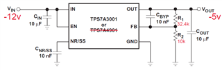
- Regulator configured for -5v output per table in specification sheet with supporting input/output 10uF capacitors and 10nF Cbyp and Cnr/ss capacitors.
- Failure is no output after soaked in humidity whereas the -5v goes to zero volts
- Upon Failure it is noticed that the NR/SS voltage measures ~-6VDC where in normal operation it measures -1.2VDC
- IC does not self-correct itself over time, however, will present a proper output again when power is cycled over time.
- Circuit schematic shown below
Additional Testing has been done of your TPS7A30 evaluation fixture which holds the TPS7A3001DGNT
- Different package configuration
- Regulator on fixture is also configured for -5v output
- Does not present failures at high humidity (running much longer test over weekend)