This thread has been locked.

If you have a related question, please click the "Ask a related question" button in the top right corner. The newly created question will be automatically linked to this question.

BQ25896: Weird behavior of NTC fault, INT and STAT pins?

Part Number: BQ25896

Tool/software:

Hi,

We are developing a product using the BQ25896, and we have observed some strange behavior related to the NTC fault: we frequently read the fault register, and after some time, the NTC status oscillates between "hot" and "normal". More precisely, the register reports "NTC hot", then, in subsequent reads, it reports "normal", then reports "NTC hot" again once, etc, with a variable period between 1 and 10 seconds.
We expect the NTC fault to remain at "hot" if the battery is indeed hot, in accordance with §9.2.16.7 of the datasheet: " The only exception is NTC_FAULT which always reports the actual condition on the TS pin".
However, the battery we were using was nowhere near 60°C, so we should not be seeing "NTC hot" at all.
VBUS was unplugged, but this also occurred a few times with a 4.2V VBUS.

When testing with the BQ25896's evaluation board, we were able to reproduce the same issue consistently, both with VBUS off and at 4.2V. We had to set JP10 off and JP8 on to force the oscillation though. We narrowed the issue down to a simple configuration - the default one - with the watchdog disabled and continuous ADC conversion enabled.
Some interesting observations:
- the frequency of the oscillation increases when we sample the NTC fault more frequently (this is not the I2C frequency). For instance, sampling 5 times per second causes the NTC fault to oscillate with a 1s period. Sampling it only twice per second results in an oscillating period of ≈5 seconds. The INT and STAT pins also oscillate (see the first two images below), with varying duty cycles. STAT sometimes fades away and stops pulsing (duty cycle drops to 0%), while the issue still persists, making the STAT output unusable for our application. Since the jumpers are configured to force NTC to "hot", we expected to read "NTC hot" continuously and for the STAT pin to blink at 1Hz (as described in §9.2.16.7 and Table 5).
- we tried reading the value of CONV_START to see if ADC conversion was ongoing while reading the NTC fault. CONV_START was more often 1 than 0 when we observed "NTC hot", though this is hard to confirm due to the delay between reads.
- the issue seems to be resolved when switching to one-shot ADC conversion, and manually writing/reading CONV_START before reading the NTC. In that case, NTC fault stays at "hot" and STAT blinks at 1Hz with a 50% duty cycle, as expected.
- the issue also seems to disappear when VBUS goes above 4.3V. NTC fault remains "hot" and STAT blinks at 1Hz with a 50% duty cycle, as expected.

This leads us to assume that when ADC conversion is active, the NTC value may not be reliable and does not persist correctly in the internal state machine. However, we cannot explain the last point.
What is your opinion on this? Do you have any insight into why this occurs?
If our conclusion is correct, do you have a workaround for this issue, other than using CONV_RATE at 0 (which we would prefer to avoid)?

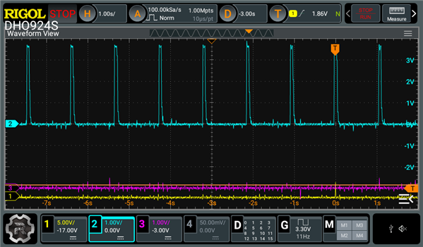
Captures of the logic analyzer output on the BQ25896-EVM664: Channel 0 & 1 are I2C, channel 2 is INT pin, channel 3 is STAT pin.

What was obtained while the battery was plugged: INT pulses, in sync with the oscillation of the NTC fault observed

What was obtained in the same situation, while the battery was unplugged:

Also, when VBUS was on, and we were unplugging and plugging the battery, the INT pin and STAT pin would start pulsing at 11Hz, which seems similar to this (unanswered) issue. This occurred with JP9 and JP10 on (NTC was measured as normal, as expected this time).
Do you have an insight on what could cause this?

STAT and INT at 11Hz.
The CHRG_STAT oscillates between "fast charging" and "charge termination done"

  • Hi,

    We are working on it and will get back to you soon.

    Thanks,

    Ning.

  • Hi,

    When ADC is enabled, it may impact on VT1 and VT5 thresholds and cause charging on and off. Disabling ADC or using one-shot ADC as less as possible when VTS is close to VT1 and VT5 should help.

    Thanks,

    Ning

  • Hi,

    Thank you for your quick response.
    I made additional measurements on VTS and VREGN to check whether I am indeed close to one of the thresholds, but it doesn't seem to be the case. I still observe oscillations, with the NTC being reported as normal, hot or cold unexpectedly, depending on the situation. For instance:

    • With VTS = 0 V and VREGN = 3.23 V, the reported percentage in TSPCT is 21% (the minimum value that can be returned), which seems far from VT1 (≈34%). NTC is reported as "hot" only once every 5 measurements, and "normal" the rest of the time.

    • With VTS = 2.86 V and VREGN = 3.25 V, the reported percentage is 80.055% (the maximum value that can be returned), which seems far from VT5 (≈73%). NTC is reported as "cold" only once every 5 measurements, and "normal" the rest of the time.

    Does enabling the ADC have that much impact on just the NTC value?
    Note that during the tests, the TSPCT value does not change at all, so I would not expect the NTC status to change either.

  • Hi,

    Do you have a waveform of the VTS voltage to confirm there isn't some unexpected voltage change on the pin voltage? The ADC can have a notable impact on VT1 and VT5 thresholds. Does disabling the ADC have an impact on the frequency with which Hot and Cold are reported in your testing?

    Best Regards,

    Juan Ospina

  • Hi,

    Thank you for your patience.
    I took some voltage measurements of VREGN and VTS.
    Channel 2 (blue) represents VREGN, and Channel 3 (magenta) represents VTS, with a scale of 1 V per division.
    The first channel (yellow) shows a pulse when the first correct NTC fault value is returned ("hot" or "cold", depending on the test case) after 10 seconds of communication (so you can see what the signals look like over a longer period). Afterward, the next few values read as "normal", which is not the expected one in either test case.

    I have attached the raw waveform files if you want to take a closer look.
    I also included the logic analyzer output (DSView). The first two channels are the I2C lines, and the third is the INT pin. Channel 4 is STAT. Channel 5 is unused, and channel 6 shows the same pulse as the first channel on the oscilloscope, for synchronization.

    Best regards.

    ↑ Voltages measured when JP9 and JP8 are on (to emulate a hot NTC). Channel 3 is very close to 0V during the whole test.

    hot1.csv Waveforms

    DSLogic U3Pro32-hot-detection.txt DSView file (extension changed from .dsl to .txt to be able to upload it)

    ↑ Voltages measured when JP9 is on (to emulate a cold NTC)

    cold1.csv Waveforms

    DSLogic U3Pro32-cold-detection.txt DSView file (extension changed from .dsl to .txt to be able to upload it)

  • Hi,

    We are working on it and will get back to you soon.

    Thanks,

    Ning

  • Hi,

    Enabling the ADC impacts on the TS comparator operations. Please avoid using ADC when VTS is closer to the hot/cold thresholds.

    Thanks,

    Ning.

  • Hi,

    Thank you for your response.
    I am a bit confused, however, because the VTS voltages tested in this case seem quite far from VT1 and VT5 — there is a difference of up to 13% in my case.
    Do you have any recommended gap values between the thresholds and VTS/VREGN when the ADCs are enabled?

    Best regards.

  • Hi,

    It depends on the thermistor selected and RT1/RT2 values etc. Please use the measurements on your specific design boards.

    Thanks,

    Ning.