This thread has been locked.

If you have a related question, please click the "Ask a related question" button in the top right corner. The newly created question will be automatically linked to this question.

Continuous FAULT condition

Part Number: UCC256403


Tool/software:

Hi,

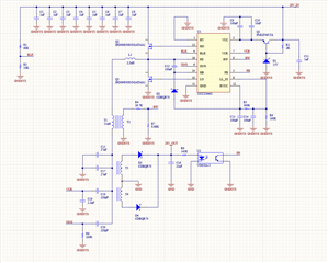
we are designed a LLC power supply with UCC256403.

Specifications: 24-32 V DC Input - 28 V Out - 10 W MAX

Attached the complete schematic. 

The controller start and then enters a continuous FAULT conditions every 1s. RVCC goes from 13 V to 0 V every second.

No load into the output.

We can't figure out why this thing enters immediately in a FAULT, without load and with a proper setup I think, configured directly from design calculator by TI.

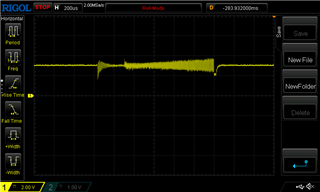
Here also pictures from the scope of the SW node, OUT node, ISNS, VCR

Please, can someone have a look to schematic and images and help me?

  • Can you please share your design calculator?

    Looks like your Vout is not zero at the beginning. Does it mean you can power up but then it restarts?

    Please capture the start up waveforms.

  • Hi, 

    in the second picture it is not Vout, but the resonator out (C15, C17 node), and there is a DC voltage, yes.

    It can power up and then it restarts.

    Anyway I solved this first problem shorting BW pin to GND, now at least it starts and I have output voltage, even if it can't enter burst mode.

    Any idea why shorting BW solved the problem? Maybe an over voltage shoot at startup ?

    However now there is a second problem, it starts but the input current with no load is 100 mA! So I have 2.8 W of power taken from this thing going directly in heat into the transformer that of course overheat in a while. I thinks this is not a normal behaviour and I need your help to understand.

    Attached the design calculator.

    2112.UCC25640x Design Calculator Rev4.0.xlsx

  • It is recommended to add a capacitor on the T2 terminal to reduce the noise to avoid false trigger of OVP. Please refer to the datasheet and EVM schematic.

    If you tie BW to ground, it will draw current on each half switching cycle. This is where your power burn coming from.

    I'd suggest not to tie BW to ground but add the cap as I suggested.

    Again, please overlay as many waveforms in one image as possible for future reference.