This thread has been locked.

If you have a related question, please click the "Ask a related question" button in the top right corner. The newly created question will be automatically linked to this question.

TPS65300-Q1: Redundant Power Tree Design Using TPS65300-Q1 — Behavior of VSENSE Pins Before EN Assertion

Part Number: TPS65300-Q1
Other Parts Discussed in Thread: TMS320F28377D

Tool/software:

Hi TI Team,
I’m working on implementing a redundant power supply architecture using the TPS65300-Q1 PMIC, which I intend to activate only in the event of a failure in my primary power supply (a set of buck converters providing 1.2V, 3.3V, and 5V).
Use Case Summary:

  • The primary rails (1.2V, 3.3V, 5V) are generated by discrete buck converters.
  • These rails power a C2000 microcontroller (TMS320F28377D) and supporting peripherals.
  • I have the option to place diodes at the output of the buck converters, and the plan is to use the PWRGOOD signal of each buck to monitor failures.
  • In case of failure, I’ll use the PWRGOOD signal to control the EN pin of the TPS65300-Q1, enabling the backup supply.
  • The diode ORing is done only at the output of the bucks — I have not placed diodes at the output of TPS65300-Q1, primarily to avoid voltage drops that I can’t easily compensate with feedback or margining.

Questions:

  1. Behavior of VSENSE Pins Before EN = High:
    Since the TPS65300-Q1 isn’t enabled under normal operation, but the system’s 1.2V and 3.3V rails are already live from the primary supply, will applying voltage to the 1.2VSENSE and 3.3VSENSE pins before EN is asserted cause any issues?
    1. Will this lead the device to erroneously detect a fault or go into a fault state, possibly delaying or blocking turn-on when the EN pin is eventually pulled high?

  2. Does the IC assert any signal or condition based on VSENSE when EN is low?
    I’m wondering if the PMIC might try to act on or monitor the VSENSE pins even before it's actually enabled. Does the device assert low (sink current or pull-down) on VSENSE pins when EN is low?
    This could break the power ORing behavior or cause unexpected power-up delays.

  3. If needed, can I use a similar diode + feedback compensation strategy as I would with a buck converter—i.e., put a diode at the output and adjust the internal feedback to regulate post-diode? I realize this is non-trivial for PMICs and may not be supported if I connect the VSense pin after the diode.

Would appreciate your insight on this strategy and any advice or application note reference if available.

Best Regard,
Dhaval Ravat

Attachment: https://drive.google.com/file/d/1SAC5Xq6n-QrIDkEZTa7144KCtbl2y6Ja/view?usp=sharing

  • Hi Dhaval,

    Device expert Sarah is out this week and will reply when she is back in office next Monday. 

    Sathish

  • Hello Sathish,
    Hope this thread is still active. I'm awaiting feedback from the TI team on the PSU architecture. Hope to hear from the team soon.

    Best Regards,
    Dhaval Ravat

  • Hi Dhaval, 

    Thank you for your patience, apologies for the delay. 

    I see no issue with the VSENSE pins being HIGH while EN is LOW.
    The device does not monitor or flag any sort of fault for this behavior

    When EN is eventually asserted, the VSENSE should be low since the external bucks are not outputting, so I don't see there being a conflict here. 

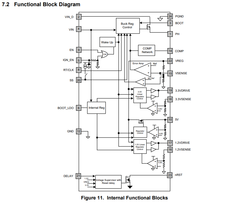
    The internal regulator controls will only act when the wakeup signal is sent from EN being enabled, so the status of the VSENSE pin should not effect the IC while EN is low:

    Please be wary that this is not typical recommended application case for this device, and this function has not been under extensive testing. 
    And unfortunately we do not have any reference materials or application notes for this such case. 

    Best Regards, 
    Sarah

  • Thank you very much for your response — it helps clarify a lot of my concerns!

    When EN is eventually asserted, the VSENSE should be low since the external bucks are not outputting, so I don't see there being a conflict here. 

    In the architecture I attached earlier, if any of my primary buck converters (3.3V, 1.2V, 5V) fail, I plan to assert the EN pin of the TPS65300-Q1 high to activate the secondary (redundant) power path. To ensure a smooth transition and avoid a sudden power cut to the microcontroller, I was planning to use large output capacitors on the primary PSU rails after the ORing diodes. The goal is to hold up the voltage long enough to give the TPS65300-Q1 time to ramp up its rails (ideally ensuring no dead time during the switchover.)
    Now, in this transition, it’s likely that the VSENSE pins will still be high (due to hold-up caps on the primary PSU outputs) at the moment when EN is asserted high on the TPS65300-Q1.

    My questions are:

    1. Is this still safe/acceptable behavior for the TPS65300-Q1?
      That is, if EN is asserted while VSENSE is still high (due to capacitor hold-up), will the device still power up correctly and take control of its rails, or could this trigger any unexpected behavior?
    2. Would you recommend an alternative approach?
      For example:
      1. Should I size my output caps normally and allow the TPS65300-Q1 to act more like a clean POR (i.e., wait for the rails to fall fully)?
      2. Or (b) is it still acceptable to assert EN during the hold-up period (with VSENSE high) to minimize dead time?

    I understand this isn’t a standard application mode, but any guidance on how the device reacts in this timing window would help greatly in refining the redundancy architecture.

    Best regard,
    Dhaval Ravat

  • Hi Dhaval, 

    Understood, I didn't catch that there would be output capacitors to retain the voltage, thanks for the reminder!

    Still, I don't see an issue here. 

    1. Yes. This is still acceptable. Device will still power correctly even if there is a momentary overlap, there should not be any issue with the device starting up. 

    2. b, It will be acceptable to assert EN during the hold-up period. I don't have any proposals for an alternate approach.

    Hope this helps to clarify. 

    Best Regards, 
    Sarah

  • Hello Sarah,
    Thank you for your previous response,
    Circling back to the power tree I shared earlier, I’d like your feedback regarding soft start behavior specifically for the LDO regulators during a redundant power switchover using TPS65300-Q1.
    Since I'm using the TPS65300-Q1 as a redundant power supply that kicks in when my primary PSU (buck converters) fails. In this setup:

    • I'm using the IGN_EN pin to control when the PMIC turns on (as a switchover mechanism).
    • The EN pin is tied high (to the 5V of the PMIC itself), so it's always enabled once IGN_EN is toggled.

    My concern is with startup timing, specifically in the redundancy switchover scenario:
    The datasheet shows typical soft start time for Liner Regulators of ~13ms for 3.3V rail (section 6.7, Switching Characteristics) at Fsw = 2.5MHz and with the output initially at 0V.
    However, in my case, due to the hold-up capacitors, the VSENSE pins will already have some voltage (pre-biased condition) when the TPS65300-Q1 is enabled. The voltages will begin to droop, but not instantly fall to 0V.

    My Questions are:

    1. How does the TPS65300-Q1 behave during startup if the VSENSE/output pins are already pre-biased (i.e., not starting from 0V)?

      1. Will the PMIC still go through the full 12–13ms soft start?

      2. Will it detect the pre-biased state and complete startup faster?

    2. I am planning to size the bulk hold-up capacitors on the output rails to maintain rail stability until the TPS65300-Q1 takes over. I'm concerned that if the bulk cap is too small, the voltage might dip below the MCU’s POR threshold, causing unwanted resets during the transition.

      1. Is there any way to bypass or reduce the soft start time specifically for the LDO rails, or are they fixed internally?
      2. Would you recommend any alternative handover strategy that prioritizes voltage stability (no dip) during switchover? Or would it be better to accept a brief dip and ensure the system can handle a controlled reset?

    Appreciate your support in helping evaluate this edge use case. I understand this is not a typical configuration, but I want to ensure robustness in power redundancy without introducing instability.

    Best regards,
    Dhaval Ravat

  • Hello Dhaval, 

    Unfortunately, we do not have the data to validate the device behavior of TPS65300-Q1 when output pins are already pre-biased. 

    The soft start time of the linear regulators cannot be bypassed/altered, this is set internally. Only the soft start time of the buck is able to be adjusted via the capacitor on the SS pin. 

    This is an older device and the Evaluation Module (EVM) is obsolete. 

    I apologize for the inconvenience and being unable to offer any more insight. 
    I can say that for C2000 designs, the TPS65381A-Q1 is a newer, functional-safety part compatible with C2000 that does have an EVM available for evaluating.

    Best Regards, 
    Sarah