This thread has been locked.

If you have a related question, please click the "Ask a related question" button in the top right corner. The newly created question will be automatically linked to this question.

TPS25751: + BQ25792 as USB-PD Source and Sink

Part Number: TPS25751
Other Parts Discussed in Thread: BQ25792

Tool/software:

Hello!

We are currently investigating a solution for a product.

I have come across the TPS+BQ implementation for USB PD and wanted to ask some questions.

But first up some design goals:

  • 4S (13,6-16,8V) Battery max charge current 2,75A
  • max System load 100W - (6,25-7,4A discharge through SysFet)
  • USB-C PD compliant
  • Sink: max 100W if availabe
  • Source: 60W max

1. The first question we have is why the TPS needs an additional 5V supply when the BQ could just provide that? When is this 5V supply loaded? Only for the 5V 3A USB-PD sources or just for the BC1.2? Why doesnt the TPS just request 5V from the BQ in USB OTG mode?

This would save some boardspace, cost and added complexity.

Additionally: when is the 5V needed to be present? Is there a way to configure the GPIOs of the TPS to disable/enable the 5V converter only when its needed?

We imagined to have a simple system where our load is supplied by the Vsys output of the BQ, switched by a hard power button with no uC running in standby. 

We would have liked to have a single 5V converter (we are very weigth/space constrained) which would supply the TPS/USB and our main uC load. However this would mean that the 5V wouldnt be availabe when the device would be switched off. So USB - PD source only avaiable when the device is on. Is this possible? (we want to have low parasitic drain and dont want to have a 5V stepdown running all the time)

2. What happens if a too low wattage USB-PD source is connected? Does the TPS configure the BQ to just draw whats availabe?

Thanks and have a nice day

Stephan Schwarz

  • Hi Stephan,

    1. The first question we have is why the TPS needs an additional 5V supply when the BQ could just provide that? When is this 5V supply loaded? Only for the 5V 3A USB-PD sources or just for the BC1.2? Why doesnt the TPS just request 5V from the BQ in USB OTG mode?

    This would save some boardspace, cost and added complexity.

    Additionally: when is the 5V needed to be present? Is there a way to configure the GPIOs of the TPS to disable/enable the 5V converter only when its needed?

    The 5-V supply is used for Sourcing 5-V and for providing 5-V power to VCONN, which is the type-C cable power. PP5V is required to be supplied for sourcing, with a minimum of 600mA for VCONN support. We have the option to configure the 5V USB-C PD contract to be sourced through either PP5V or PPHV. If you decide to source 5-V contracts through PP5V, the 5-V rail needs to be sized to support the max 5-V contract (typically 15-W).

    The part was not designed with an internal LDO for the 5-V rail so it is required to have an external one.

    The 5V rail should always be present when the TPS25751 is configured to source. For Sink-only applications, it is not required. No, there is not a way to configure the GPIOs to disable/enable the 5V converter, and MCU or EC would be needed to control this.

    2. What happens if a too low wattage USB-PD source is connected? Does the TPS configure the BQ to just draw whats availabe?

    Correct, the TPS25751 will negotiate the highest power PD contract that both the USB-C PD Source and the TPS(as the USB-C PD SInk) support. Once an active contract is negotiated, the TPS25751 programs a compatible BQ device according to the active contract.

    Thanks and Regards,

    Chris

  • Hi Chris,

    thanks for your anwser.

    Looks like i completely missed the USB-C specs requirement for Vconn to be always present.

    But your anwser opens another question, How do you configure the TPS25751 to supply only Vconn from the PP5V supply?

    I couldnt find anything in the USBCPD Application Customization tool. (Also not in Advanced Config)

    Maybe we can "abuse" the dead battery feature to our advantage, lets assume our block diagram looks like this:

    Lets also assume that the VIN_3V3 is generated from an LDO connected to the System 5V source - so it will only be present when the device is "On" e.g. the user flipped the S1 switch.

    If I understand the documentation fully, than i expect the following behavior:

    If S1 is off and therefore there is no PP5V or VIN_3V3, the TPS25751 should be in dead battery mode. It should request 5V from USB-C PD and start running. It can only act as a sink, but I am not sure if it would still request the full configured say 100W PD contract? 

    If S1 is on and PP5V and VIN_3V3 is availabe, the TPS should be able to sink and source depending on the connected and agreed on PD contract.

    What happens if PP5V and VIN_3V3 becomes availabe when the TPS25751D is already in the dead battery mode?

    Do we really need to have an embedded controller to reset the dead battery bit?

    We might be able to do some simple logic stuff (to clear the dead battery mode bit) like resetting the TPS trough I2Ct_IRQ when configured as PD Hardreset?

    Thanks and have a nice day

    Stephan

  • Hi Stephan,

    Looks like i completely missed the USB-C specs requirement for Vconn to be always present.

    Slight correction here, I realized the way I worded it might be a little confusing.

    The 5-V supply is used for Sourcing 5-V and for providing 5-V power to VCONN, which is the type-C cable power. PP5V is required to be supplied for sourcing, with a minimum of 600mA for VCONN support.

    Vconn is not always required. When sourcing, VCONN is only required when you need to source current greater than 3-A, as the cable needs to advertise >3-A current capability, and needs to be powered(by VCONN) to do so. If you are sink only, VCONN is not needed unless you need to communicate with the cable.

    The TPS25751 requires PP5V when doing any sourcing, not necessarily because of the VCONN requirement.

    How do you configure the TPS25751 to supply only Vconn from the PP5V supply?

    VCONN is automatically supplied through PP5V. What you can change is how the 5-V PDO is supplied.

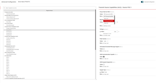
    When you configure Source PDO 1 in the "Transmit Source Capabilities" register, there is an option to change the power path.

    PP1 corresponds to PP5V, and PP3 corresponds to PPHV. If you want the TPS25751 to supply VCONN only from PP5V, change the power path to PP3 so the 5-V source PDO is supplied by through the PPHV power path.


    If S1 is off and therefore there is no PP5V or VIN_3V3, the TPS25751 should be in dead battery mode. It should request 5V from USB-C PD and start running. It can only act as a sink, but I am not sure if it would still request the full configured say 100W PD contract?

    Not completely true.

    Technically, the device is just off at this moment.

    The moment a plug is connected, the TPS25751 (in the off state) exposes Rd resistors on the CC lines which advertises the port as a Type-C sink, and if a Type-C source is attached, 5-V should be provided on VBUS per a basic Type-C connection. Once the TPS25751 powers on from VBUS, we are in "dead battery mode" and an internal dead battery flag is set.

    Now, depending on your dead battery config, the PD controller will have slightly different behaviors. You can read the full descriptions in table 8-6 in the DS.

    If you have an I2C EEPROM holding the config, the PD controller will supply LDO3V3 off of the VBUS power, and the EEPROM should get power from LDO3V3. Then the TPS25751 will load its config from the EEPROM and act as a sink according to the config settings. If the configuration supports 100-W sink PD contracts, it will attempt to negotiate up to a 100-W contract. (depends on what the source offers).

    So yes, it initially requests a Type-C 5-V contract, but can boot and request a 100-W PD contract depending on the configuration in the EEPROM.

    If S1 is on and PP5V and VIN_3V3 is availabe, the TPS should be able to sink and source depending on the connected and agreed on PD contract.

    If this happens first, yes. You are also assuming that a valid configuration has been loaded to the PD controller (either from the I2C EEPROM or an I2C host)

    What happens if PP5V and VIN_3V3 becomes availabe when the TPS25751D is already in the dead battery mode?

    The dead battery flag is still asserted and the device stays in it's current operational mode and is still in "dead battery mode". The device is still sink only.

    Do we really need to have an embedded controller to reset the dead battery bit?

    Not necessarily, but options are pretty limited here.

    There is a single configurable GPIO event "Barrel_Jack_Event", that when asserted will set the fields mentioned, clear the dead battery flag, and will also trigger a power role swap to source.

    There is unfortunately no GPIO for just clearing the dead battery flag.

    We might be able to do some simple logic stuff (to clear the dead battery mode bit) like resetting the TPS trough I2Ct_IRQ when configured as PD Hardreset?

    I'm not sure what you mean by this. You cannot configure the IRQ to trigger a behavior in the PD controller.

    Thanks and Regards,

    Chris

  • Hi Chris,

    thank you very much for your lengthy explaination!

    We would really like to not have an EC / uC connected to the device so all the behavior should be assumed to be with an EEPROM for configuration - no I2C comunication.

    Just to recap if i really got everything you said:

    1. If we limit the max PD power source to 60W total with 3A max, and we set the right config (sourcing from PPHV) we dont need to have a 5V source thats capable of 3,6A in our system.

    We would only need to supply the TPS 5V for its own internal supply - I assume this to be a few mA but couldnt find the exact value in the datasheet.

    Vconn would never be needed because an active cable wouldnt be needed <3A.

    Not sure what would happen if an active cable would be connected? I assume it just wouldnt get powered but source and sink would still be able to comunicate a 3A contract?

    Maybe we still need a 5V source to also use active cables but it would only need to provide 600mA not the full 3,6A.

    2. Clearing dead battery flag:

    We might be able to do some simple logic stuff (to clear the dead battery mode bit) like resetting the TPS trough I2Ct_IRQ when configured as PD Hardreset?

    That was a mistake. I didnt read properly.

    Do we need to clear the dead battery flag? What happens if the usb-c source is disconnected when the bit is set and PP5V became available? Is it reset when PP5V is available on the next plug event or does it never get reset by any sleep/standby/idle mode?

    That would mean -> device off (PP5V no voltage) = only sink / device on (PP5V present) = sink & source

    So to change from sink (dead battery mode) to source you would need to supply PP5V and reconnect the usb-c device.

    This behavior would actually be really benefical as it would mean we could set the TPS to "source prefered" role and let the user select source/sink based on if the device is on or off / was pluged in before turnon.

    If thats not the case you seem to imply that we could configure a GPIO to "Barrle_Jack_Event" and toggle it momentarily to clear the flag?

    However if the bit is not cleard by a plug event with PP5V present, the bit should still be cleared by powercycling the device e.g. removing the PD source and switching PP5V off to completely turn off the TPS. (Clearing the bit) If the device is now switched on (PP5V now present) the TPS would now be able to source and sink. Correct?

    I assume some of my questions would be anwsered if i could understand the Table "8-7. Power Consumption States" in the datasheet. However i dont quite get what it means. I also cant find how big time (T) is - mentioned just above the table.

     Stephan

  • Hi Stephan,

    1. If we limit the max PD power source to 60W total with 3A max, and we set the right config (sourcing from PPHV) we dont need to have a 5V source thats capable of 3,6A in our system.

    We would only need to supply the TPS 5V for its own internal supply - I assume this to be a few mA but couldnt find the exact value in the datasheet.

    Vconn would never be needed because an active cable wouldnt be needed <3A.

    Not sure what would happen if an active cable would be connected? I assume it just wouldnt get powered but source and sink would still be able to comunicate a 3A contract?

    Maybe we still need a 5V source to also use active cables but it would only need to provide 600mA not the full 3,6A.

    Yes, you should be fine. I would recommend the 600mA just to be safe, but this could be an LDO instead of a buck needed for the 3-A.

    Do we need to clear the dead battery flag? What happens if the usb-c source is disconnected when the bit is set and PP5V became available? Is it reset when PP5V is available on the next plug event or does it never get reset by any sleep/standby/idle mode?

    You need to clear the dead battery flag if you want to source. For sink-only, the dead battery flag can remain set.

    The Dead battery flag is only reset on the "DBFG" 4CC command(I2C), the Barrel Jack Event (GPIO), or if there is a power cycle and the PD controller comes up in a non-dead battery state (power from VIN3V3). Enabling or Disabling PP5V will have no effect on the Dead battery flag state.

    Device power is controlled by VIN3V3, not PP5V. PP5V provides 5-V for cable power and sourcing requirements, but is not used to actually power the IC itself.

    Do we need to clear the dead battery flag? What happens if the usb-c source is disconnected when the bit is set and PP5V became available? Is it reset when PP5V is available on the next plug event or does it never get reset by any sleep/standby/idle mode?

    That would mean -> device off (PP5V no voltage) = only sink / device on (PP5V present) = sink & source

    As mentioned above, there are only really 3 ways to deassert the dead battery flag. "DBFG", Barrel Jack Detect GPIO, and power cycling VIN3V3.

    To change from sink to source(using power rails), you would need to disconnect the source, then remove and reapply VIN3V3 to re-boot the PD controller. Basically, if the PD controller boots from VBUS power (no VIN3V3), the dead battery flag is set. If the PD controller boots from VIN3V3(and not VBUS), the dead battery flag is not set.

    This behavior would actually be really benefical as it would mean we could set the TPS to "source prefered" role and let the user select source/sink based on if the device is on or off / was pluged in before turnon.

    If thats not the case you seem to imply that we could configure a GPIO to "Barrle_Jack_Event" and toggle it momentarily to clear the flag?

    If you want to clear the dead battery flag using the Barrel Jack Event, it is recommended to assert and keep the GPIO high, not to toggle.

    However if the bit is not cleard by a plug event with PP5V present, the bit should still be cleared by powercycling the device e.g. removing the PD source and switching PP5V off to completely turn off the TPS. (Clearing the bit) If the device is now switched on (PP5V now present) the TPS would now be able to source and sink. Correct?

    Replace PP5V with VIN3V3 and it should be correct.

    I assume some of my questions would be anwsered if i could understand the Table "8-7. Power Consumption States" in the datasheet. However i dont quite get what it means. I also cant find how big time (T) is - mentioned just above the table.

    This table is more for power states and not specifically for Dead Battery, it would not help much here.

    Thanks and Regards,

    Chris

  • Hey Chris!

    Again thank you very much for helping me better understand this rather complex IC!

    I would have gone ahead and generated (LDO) the VIN3V3 directly from PP5V - thats why i referred to it. I didn’t clarify that sorry!

    So far so perfect! This solution should allow us to do everything we want.

    Just one last question:

    I couldn’t quite understand what "Barrle_Jack_Event" does. It clears the Dead Battery flag but it also sets PORT_CONTROL.UnconstrainedPower and TX_SCEDB.SourceInputs[0] to true or false depending on rising/falling edge.

    However what does that do? I assumed it would communicate with the BQ25792 that it should use its alternative power input and draw as much current as it needs (trough VBUS) to reach the programmed charging current + Sys load.

    That doesn’t seem desirable as it would overload the USB-C source? Thats why i assumed toggling the pin to just reset the Dead battery bit but not actually go into an unconstrained power state.

    Maybe i am completely wrong about my assumption!

    Thanks and have a nice day

    Stephan

  • Hi Stephan,

    Unconstrained power and SourceInputs are PD messaging specific bits that indicate the power capability of the system. Just if there is unconstrained power or not. It's mainly for communication.


    I do have to make a correction, the Battery Flag clear does not necessarily initiate a power role swap.

    What it really does it that now you have system power and do not need dead battery, it will initiate a VBUS disconnect to renegotiate the contract.

    If you have the "Initiate swap to source" bit set in the "Port Control 0x29" register, on renegotiation it will try to negotiate the port to be a source.

    If you don't have this bit set, the port will come in the configuration set in "Port Config(0x28) -> Type-C State Machine".

    That doesn’t seem desirable as it would overload the USB-C source? Thats why i assumed toggling the pin to just reset the Dead battery bit but not actually go into an unconstrained power state.

    It should not overload the USB-C source. If the "initiate" bit is set, it may request a power role swap to source, but the Type-C source can reject it if the Type-C source is source-only.

    On renegotiation, the ports will negotiate roles according to what is supported by both ends, there should be no "forcing" of the power roles.

    To summarize, the "Barrel_Jack_Event" on rising edge will clear the dead battery flag and set the unconstrained power and source inputs fields high or low depending on the rising/falling edge. On rising edge, it also triggers a renegotiation of the connection on the type-c port.

    Depending on the state of the "Initiate swap to source" bit, it may try to become the power source, but if the device connected on the Type-C port is power source only, the TPS25751 will not force anything and will likely end up as power sink.

    Toggling it may be fine, but it will deassert the two fields.


    However what does that do? I assumed it would communicate with the BQ25792 that it should use its alternative power input and draw as much current as it needs (trough VBUS) to reach the programmed charging current + Sys load.

    The primary thing that this does is it disables the dead battery flag which would allow the PD controller to swap to source.

    It does not communicate with the BQ25792 at this time to tell it to use alternative power draw.

    Thanks and Regards,

    Chris

  • Thank you very much Chris!

    Issues solved / all question answered!

  • Great, feel free to submit a new E2E thread if you have any more questions.

    Closing this thread now.

    Thanks and Regards,

    Chris