This thread has been locked.

If you have a related question, please click the "Ask a related question" button in the top right corner. The newly created question will be automatically linked to this question.

TUSB542: USB3 connection not working

Part Number: TUSB542
Other Parts Discussed in Thread: TUSB321, , HD3SS3212, HD3SS3220, TUSB1044, TUSB544, TUSB211A

Tool/software:

Good Afternoon,

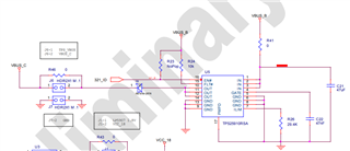
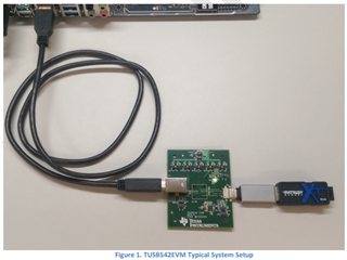
We made a board based on the design of the TUSB542 Evaluation Module, with the difference that we couldn't fit an USB type B so we replaced it by a USBC (the cable being USB3 A to C).

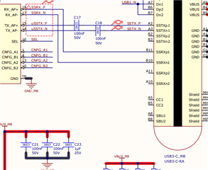
But the high speed (USB3) doesn't work, there is no signal on the RX_AP and TX_AP, only on the USB2 (D line) that is connected directly.

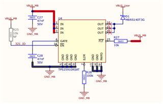
Upon further inspection I noticed that my RX_AP and TX_AP are swapped (because I followed the pin names, not number, and didn't realize they were different from the TUSB542 datasheet). Another difference is the resistor for the TUSB321 Current Mode, that instead of the original 10k I made it 200k, but this should only decrease the current, not the functionality.


We modified a cable to swapped RX and TX (easier than modifying the PCB while maintaining a good impedance match), but it didn't work.

Any idea on what the problem may be?

We also checked the voltage suppliers and they are ok.

Thanks,

Camila

PS: The TX1 on the eval board are connected with the opposite polarity, but it shouldn't make a difference.

  • Hi Camila,

    Could you send over the schematic for the TUSB546 and the TUSB321? I would like to review those and make sure everything is setup correctly there.

    Also, if you could monitor the CC, ID, and DIR lines, I would appreciate it. The DIR pin should be toggling depending on the orientation of the CC lines.

    Thanks,

    Ryan

  • Hi Camila,

    If you could send the schematic for your board, or at least the sections with the relevant devices, that would be better. I understand you used the TUSB542EVM as your base, and even if you just used that EVM design exactly the same, it would still be better for me to review that, just to confirm its all setup right.

    One thing I would like to note, if you replaced the type-B port with another type-C port, you will have to use a CC controller for that port as well. There needs to be a CC controller on each type-C port, that way proper type-C communication can take place over the CC lines. If you only have a CC controller on the downstream facing port, the upstream-facing port, the one you replaced the type-B port with, will either only work in USB3 in certain orientations, or will only work with USB2.

    Thanks,

    Ryan

  • TUSB542_Schematic.pdf

    Hi Ryan,

    Here our schematic (sorry, thought we could only add links here), does the CC line maters even if you are using a USB3 A to USB3 C cable? It has the same pins as USB3 B.

    Thanks,

    Camila

  • Hi Camila,

    does the CC line maters even if you are using a USB3 A to USB3 C cable? It has the same pins as USB3 B.

    Yes, CC lines are still important. These are still used to determine the orientation of the type-C plug, which the CC controller typically uses to control the orientation of a mux or redriver mux, like the TUSB542 in this case. The CC controller on the EVM controls the SEL pin on the TUSB542, telling it which pins of the type-C connector currently have the SS connection routed through it, that way it can pass the data through the device correctly.

    In the design you have currently, because there is not a CC controller connected to the CC pins or a mux pathing the TX/RX pins to the CC controller, your Type-C cable will either only work in one orientation, or it will not work at all, only working at USB2 speeds, like you're seeing now.

    Between U1 and the motherboard-facing type-C connector, you need another CC controller connecting to the connector, and a USB3 mux that can interact with the CC controller to mux the USB3 signals from the TX/RX_AP pins to the correct SSRX pins on the connector.

    For that type of applications, my recommendations would be to either use the TUSB321 CC controller with the HD3SS3212 type-c mux, or use the HD3SS3220, which is a CC controller and type-C mux in one device.

    Alternatively, you could also look at using the TUSB544 or TUSB1044, but you would still need a CC controller to control that downstream-facing port.

    Another important point is that with this downstream-facing port, VBUS should not be sent through the port at all times. Typically, CC negotiation needs to take place between the CC controllers on either side of the downstream-facing connector, and that negotiation will indicate when VBUS needs to be sent. In the case of the TUSB321, when a connection is made when it is set to DFP and CC negotiation begins, the ID pin will go low, indicating VBUS can be sent down the USB-C port. Typically, this ID pin is connected to something like a VBUS switch or MCU, which will monitor that ID pin and send VBUS once it sees ID go low, like in the TUSB542EVM:

    As your design is now, my expectation would be for the type-c cable to maybe work in one orientation, or not work at all, only working in USB2 HS. Without adding a CC controller and a mux to help route the USB3 signals to all pins on the connector, I am not sure there is any way for USB3 SS signals to work correctly with this connection.

    I know I threw a lot at you in this response, so if you have any questions or need any clarification, please let me know!

    Thanks,

    Ryan

  • Hi Ryan,

    Thanks for the detailed reply, as a last attempt to test the board I replaced the USB C for the USB B connector (on the TX/RX_AP side, like in the Eval Board), but even in this case I couldn't get a full speed (in neither USB C orientation).

    For the VBUS that you comment, I'm using the TPS25910RSAT in the same way as the Eval Board.

    Anything else you think I should check?

    Thanks,

    Camila

  • Hi Camila,

    You aren't seeing any USB activity in general, correct? Can you monitor VBUS on both sides of the board and ensure there are no issues there?

    Which type-C connector did you replace? The one facing the motherboard(DFP) or the one facing the User USB-C port(UFP)?

    The VBUS used between the two connectors should be the same VBUS, so please ensure that is the case. 

    Is your board connected in this style setup? Or is it connected to the PC via the type-C?

    Thanks,

    Ryan

  • Hi Ryan,

    Only the USB2 (low speed) is working, and VBUS and all the other power lines have the correct voltage.

    I replaced the USB on the motherboard side.

    Not sure what you mean by same VBUS, the VBUS from the motherboard side goes to the input of the TPS25910RSAT and the output goes to the USB connector on the user side, exactly how you do in the Eval Board, with the exception that we added some ferrite beads on the User side to filter the noise (we did the same in another working USB C board).

    We connected the same as in your picture.

    Thanks,

    Camila

  • Hi Camila,

    Not sure what you mean by same VBUS, the VBUS from the motherboard side goes to the input of the TPS25910RSAT and the output goes to the USB connector on the user side, exactly how you do in the Eval Board, with the exception that we added some ferrite beads on the User side to filter the noise (we did the same in another working USB C board).

    We connected the same as in your picture.

    And it looks like the CC controller should have the CC pins attached to the type-C port the flash drive is connected to, so that should be correct. Could you monitor the ID, DIR, and CC pins of the TUSB321 to ensure that there is activity on the CC lines, and that the TUSB321 is having the ID pin go low properly and control VBUS and the TUSB542.

    One thing I want to make sure of as well is that all the lanes are properly AC coupled. Namely, that the SSRX signals are being coupled on the motherboard side of the system, and that the RX pins are being coupled on the user USB-C side of the system. Each lane should be coupled between 75-265nF.

    Thanks,

    Ryan

  • Hi Ryan,

    The ID signal is 0V when the device/USB drive is connected (either position) and 5V when disconnected, the DIR signal is 0V for position 1 and 1.7V for position 2 or disconnected, shouldn't it be 5V? The CC lines seams to be 0V on both.

    Btw here is the mod I did (green lines):


    Thanks,

    Camila

  • Hi Camila,

    If there is communication actively going on between the CC pins, one of those CC lines should be pulled up, indicating that there is an active connection.

    the DIR signal is 0V for position 1 and 1.7V for position 2 or disconnected, shouldn't it be 5V? The CC lines seams to be 0V on both.

    For the TUSB542, the DIR pin signal should be okay, as the high level input for the SEL pin is 0.7 X VCC of 1.8V, so 1.7V should work fine. The CC lines both being 0V is odd though, typically one of them should be pulled up to something like 3.3V or 5V, especially considering it seems like the TUSB321 is working correctly

    If we are seeing issues with even getting USB2 HS to work, we could work on that as well just to make sure there are no issues there. Would it be possible for you to directly connect the VBUS's of each port to each other, that way we can confirm there is no issue there?

    Additionally, can you monitor the CD and ENA_HS pins of the TUSB211A to see how the redriver is responding? And just to confirm, the USB2 lanes are connected beneath the redriver, correct?

    Thanks,

    Ryan

  • Hi Ryan,

    True, I forgot the signal needs to go to TUSB542 that 1.8V as Vcc.

    The USB2 is working, it's being marked as high speed but the max transfer speed I got was 19 Mb/s, it's on the RX/TX of USB3 that we have a problem.

    I just did a test of using a USB-C HUB instead of connecting direct to the USB-A 3.0 port and this way the the board works, the CC line one goes to 0V and the other to 1.8V, the only problem is that it keeps disconnecting so I cant transfer any files to it, but at least is something, with that in mind we decided to make another board with this mod (USB-B 3.0 instead of USB-C) and see how it behaves.

    Thanks for the help, I'll let you know the outcome once I have the new board with me (probably in 4-6 weeks time).

    Cheers,

    Camila

  • Hi Camila.

    Okay, understood. That is weird behavior that it disconnects during data transfer, it could be a signal integrity issue then. That could be tested by adjusting the EQ on the TUSB542 if you wanted to test that.

    with that in mind we decided to make another board with this mod (USB-B 3.0 instead of USB-C) and see how it behaves.

    Thanks for the help, I'll let you know the outcome once I have the new board with me (probably in 4-6 weeks time).

    Got it. Would you like to keep debugging this in the meantime? If not, I can go ahead and close this thread.

    Thanks,

    Ryan