This thread has been locked.

If you have a related question, please click the "Ask a related question" button in the top right corner. The newly created question will be automatically linked to this question.

BQ25790: OTG Waveform question

Part Number: BQ25790

Tool/software:

Hi Jeff,

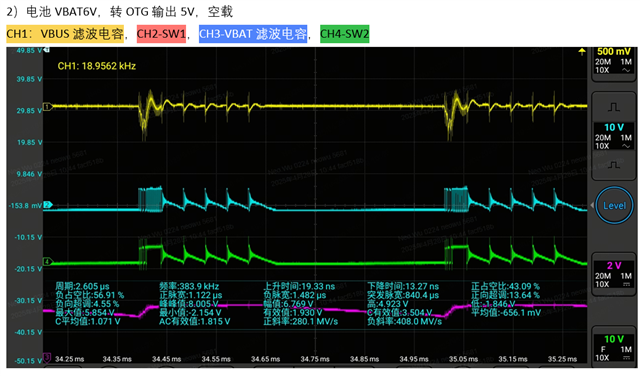
Customer meet a issue when BQ25790 in buck mode and OTG. 6V battery to power 5V Vin. They saw the duty cycle of SW are change and finally become sawtooth wave?

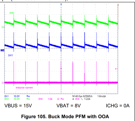
How we control each MOSFET during OTG Buck PFM mode?

Why we see sawtooth wave in SW point? This is also aligned with our DS.

Thank you,

Yishan Chen

  • Hello Yishan,

    Thanks for being patient with this. Jeff is on TBK at the moment.

    Is this waveform causing a problem for the customer?

    We'll get back to you later on this week on this behavior.

    Best Regards,
    Ethan Galloway

  • Hi Ethan,

    Thank you for your support.

    First of all, customer want to know the working principle in PFM mode(OTG Buck or Boost), they can't understand the sawtooth waveform in SW point.

    I also think it should be square wave like in PWM mode just with lower duty cycle as mentioning in Datasheet.

    Second, because of the working situation, they saw large ripple and oscillation in Vin pin, they want to know the root cause.

    Could you please help answer with the questions?

    Thank you,

    Yishan Chen

  • HI Yishan,

    I do not know the exact details but I know that our PFM alternates turning on all four switches until the inductor current reaches a fixed peak value. The PFM pulses are much smaller and because the inductor current goes to zero, the pulses will not look the same as PWM pulses in CCM.  A better comparison would be PWM pulses in DCM.  Higher input and output ripple is expected.

    Regards,

    Jeff