This thread has been locked.

If you have a related question, please click the "Ask a related question" button in the top right corner. The newly created question will be automatically linked to this question.

LM74700-Q1: Position of electrolitic capacitor in RVPP and RCB application - reference desings

Part Number: LM74700-Q1
Other Parts Discussed in Thread: TIDA-01534, TIDA-010008

Tool/software:

Hi,

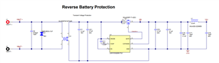
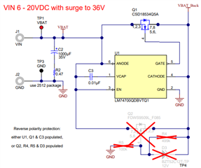
when the LM74700 part is used for the RVPP (reverse polarity protection) in an application, what do you suggest where the input bulk capacitor (polarized electrolytic) should be located, before or after the  MOSFET used in LM74700  circuit? 

Some reference designs where the LM74700 is used for the RVPP have polarized electrolytic capacitor placed before NMOSFET.
Could comment on this whether does this make sense?

Examples of reference desings where capacitor is placed before NMOSFET:

  • TIDA-01534, Automotive Off-battery Dual-phs Boost Convreter, C2 
  • TIDA-010008_DCinput_Protection, C4.
    Here is the position of the U2 confusing as well, since it is an unidirectional TVS device. 
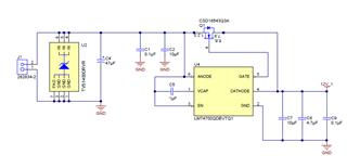
BR

Josko  


  • Hi Josko,

    You should be connecting electrolytic capacitor after the MOSFET.

    Next, the TVS is unidirectional and shouldn't be connected that way alone. During reverse polarity, it will cause a short circuit.

    Regards,

    Shiven Dhir

  • Hi Shiven, 

    thanks for answers.
    Any plans to add some notes in the documentation of these two ref. designs TIDA-01534 and TIDA-010008 regarding these two issues? 

    My next question is related to the relative position of LM74700 and EMC Filter? 
    What do you suggest regarding the position of EMC Filter and LM74700? 
    Should we follow the example in the ref. design PM21669, where CM Filter is placed the first, then RVPP and afterwards the DM filter? 
    Or there is a better solution regarding the CM, DM and LM74700 order? 
    Btw, the C1 doesn't seem to have correct voltage rating. It is 16V part and the test report states VIN 6~35V in the table 1. 


    BR

    Josko 


  • Hi Josko,

    Thanks for reporting the errors and I will make a note of it. No plans to add a note yet.

    You are correct, C1 and C2 are not correctly scaled.

    CM filter is usually placed first. CLC filters are usually placed at the output of reverse polarity protector which can be input to some other switching regulators.

    Regards,

    Shiven Dhir