This thread has been locked.

If you have a related question, please click the "Ask a related question" button in the top right corner. The newly created question will be automatically linked to this question.

BQ25185: Battery not charging, STAT2 LED always ON

Part Number: BQ25185

Tool/software:

Dear TI team,

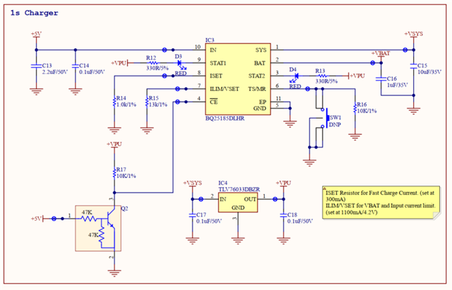
I hope you are doing well. The charger worked perfectly when my circuit was operating, but the battery suddenly stopped charging. The STAT2 LED is always ON, whether the battery is connected or not, although it should be blinking when it is not connected. The VBAT voltages are 0.47V when the battery is not connected and go to zero when the TS/MR pin push button is pressed and the STAT1 LED is not turned ON.
Please provide instant support on this matter.

I am looking forward to hearing back.

Regards,
Ahmed Ali

  • Hello Ahmed,

    Thanks for reaching out.

    The following are expected behaviors of the device:

    • When the battery is disconnected, STAT1 will be HIGH (LED1 off) and STAT2 will toggle between HIGH and LOW (LED2 blinking) as the capacitor on the BAT pin charges and discharges (refer to Figure 9-2 of the BQ25185 datasheet for an example VBAT waveform when no battery is connected). This causes the device to toggle between reporting that charging is in progress and that charging is complete.
    • While the push button on the TS/MR pin is pressed, it's expected that VBAT goes to 0V, STAT1 is LOW (LED1 on), and STAT2 is HIGH (LED2 off).

    It's possible that charge termination is being disabled as a result of VINDPM, DPPM, or thermal regulation being active when no battery is connected (refer to section 8.1.1.5 of the BQ25185 datasheet). In this case, when termination is disabled, VBAT will be held at VBATREG, and the device status pins would report that normal charging is in progress (STAT1 = HIGH, STAT2 = LOW), which seems consistent with the behavior you're observing.

    To help confirm this, could you provide waveforms of VBAT, VSYS, VIN, and ISYS (as many of these as you can) when the battery is disconnected or when the issue during charging occurs? It would also be helpful if you could clarify when you're seeing VBAT = 0.47V and what your expected system load is.

    Best regards,

    Alec

  • Hi Alec Lehman,

    Please find the attached images when the Battery is not connected to the charger:

    1. VIN

    2. VSYS

    3. VBAT

    5. Circuit when the Battery is not connected:

    When the Battery is connected to the charger:

    1. Battery Open Circuit Voltage

    2. Vin when the Battery is connected

    3. Vsys when the Battery is connected

    4. VBAT when the Battery is connected


    Please note that my oscilloscope has a 100- 200 mV offset (fault). I captured these waveforms based on the 300mA load on the VSYS. I didn't have the current probe so that I couldn't capture the current waveforms.

    I look forward to hearing back from you as soon as possible.

    Regards,
    Ahmed Ali

  • Hi Ahmed,

    Thanks for sharing these captures.

    VSYS is expected to be 4.5V when VIN is present. In your second capture, it looks like VSYS=5V.

    Could you clarify whether these captures were taken while the issue was actively occurring? Based on what you've shared, it doesn't appear that the charger was in VINDPM or DPPM, so it's possible the device entered thermal regulation.

    What is your input voltage and configured charge current? And is 300mA your typical system load?

    Best regards,

    Alec

  • Hi Alec,

    Yes, these were taken when the issue was occurring, and this issue is permanently appearing.
    Input voltage = 5V, charge current = 300mA 

    Regards,
    Ahmed Ali

  • Sorry to butt in on this thread, but I'm having what appears to be the same issue with the BQ25185DLHR - it refuses to charge the battery. I have ILIM/VSET configured to 100k (ILIM1100, Vbatreg=4.1V, Vlowv=3.0V), and charge current set to 59mA (5k1). There's a 10k from TSMR to GND. The device does not charge the battery, VBAT is at 0 and flat with no battery connected, VSYS works as expected (shows battery voltage with battery connected and VIN disconnected, shows ~4.5-4.7V flat with VIN connected). CE is shorted to GND.

  • Actually never mind that, I just spotted a solder defect, the TSMR was not properly pulled down as a result.

  • Can confirm everything works correctly for me, and I can exactly reproduce Ahmed Ali's problem if I make TSMR float.

  • Hi Kliment,

    Thanks for jumping in. I really appreciate it!

    If the TS/MR pin isn't being used for NTC monitoring and isn't tied to GND through a 10k, its voltage will be outside of the normal battery temperature range, which causes charging to be suspended.

    Best regards,

    Alec

  • Hi Ahmed,

    Are you using the TS/MR pin for NTC monitoring? If not, can you confirm whether it's tied to GND through a 10k resistor?

    Best regards,

    Alec

  • Hi Alec,
    Yes, I have tied it to GND through 10k.

    Please find the attached schematics for reference.

    Regards,
    Ahmed Ali

  • Hi Alec,
    Please also advise me when my battery is nearly charged. I observed that VBAT=4.144V and the STAT1 and STAT2 pins get low. Although the load is not disturbed, it remains in this state, which I removed by removing the Vin and re-inserting it.

    What is the problem, and how can it be overcome?

    Please note that I observed this on my other two separate boards during testing.

    Regards,
    Ahmed Ali

  • Hi Kliment,

    I have desoldered the resistor and replaced it with a new 10k ohm resistor, but it is still behaving the same. The issue is still persistent.

  • Hi Ahmed,

    Based on R15 = 13k in your schematic, ILIM is set to 1100mA, VBATREG is 4.2V, and VLOWV is 3.0V.

    Could you help clarify what you're seeing? It sounds like there might be two issues:

    1. The battery stopped charging for some reason, and at that point STAT2 was LOW and STAT1 was HIGH (indicating "normal charging in progress").

    2. VBAT was measured to be 4.144V when STAT1 and STAT2 went LOW. Did you mean they went HIGH? That would indicate "charge complete, charger in sleep mode, or charge disabled."

    Best regards,
    Alec

  • Hi Alec,

    The first issue we are discussing is that the battery is not charging on one board.

    On the second and third PCBA, the following event happened:
    "Please also advise me when my battery is nearly charged. I observed that VBAT=4.144V and the STAT1 and STAT2 pins get low. Although the load is not disturbed, it remains in this state, which I removed by removing the Vin and re-inserting it."
    Please note that when STAT1 and STAT2 get low, the LEDs turn on, as these pins are open-drain.

    These two issues need to be resolved. I am looking forward to hearing back.

    Regards,
    Ahmed Ali

  • Hi Ahmed,

    Thanks for clarifying. It sounds like the issue on the first PCBA is that the battery isn't charging, and on the other two PCBAs, STAT1 and STAT2 are going LOW and staying LOW until VIN is toggled.

    For the first PCBA:
    What are STAT1 and STAT2 showing when the battery is not charging? Is this the case you mentioned where STAT2 is always LOW and STAT1 is HIGH (indicating normal charge in progress), but the battery isn't actually charging?

    For the other two PCBAs:
    Refer to Table 8-2 in the BQ25185 datasheet. STAT1=LOW and STAT2=LOW indicates a non-recoverable or latch-off fault (ILIM/ISET pin short, BATOCP, or charging safety timer expiration). These faults can be cleared by:

    • Charging safety timer: Toggle /CE or input power
    • ILIM/ISET pin short: Toggle /CE or input power
    • BATOCP: Toggle VIN

    This seems consistent with what you're seeing on the other two boards.

    Best regards,

    Alec