


Other Parts Discussed in Thread: UCC28950
Tool/software:
Hi,
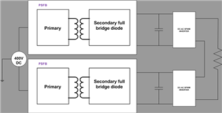
we are working on a 2 stage Multi level inverter in cascaded H bridge .it is observed that the DC link voltage starts to oscillate once the inverter starts switching.
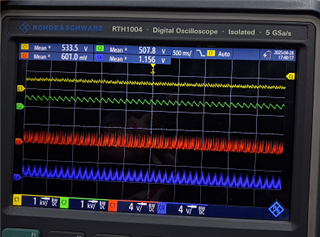
C1 and C2 are DC link voltages (yellow and green respectively) C3 & C4 are EAP signal to controller.one common reference signal is fed to both compensator reference signal at non inverting terminal.
the error amplifeir is a typ2 compensator.
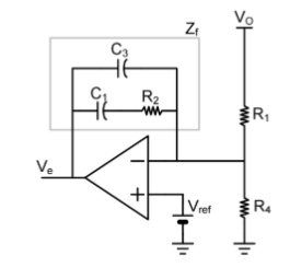
R2=100Ohms C1=.1uF,C3=1nF
R1=680 ohms R4=1k
below is the signal conditioning and compensator network from feedback divider to EAP control

Could you please share your thoughts