This thread has been locked.

If you have a related question, please click the "Ask a related question" button in the top right corner. The newly created question will be automatically linked to this question.

TPS6507X: wLED inductor and capacitor design

Anonymous
Anonymous
Other Parts Discussed in Thread: OMAP-L138, LP2985

Hi,

I would like to ask some questions with TPS6507X wLED boost converter design.

Inductance

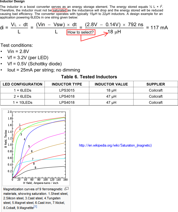
In equation (15), p.65 of TPS6507x datasheet SLVS950C, L is substituted with value 18µH. How is it determined?

On page 64, in Inductor Design says that inductor must not be saturated. The physical principle of magnetization curve is like bottom of the above screenshot.

And that

H = 0.4πNI/L I

Does that mean if I have larger current, then inductor with larger inductance might be needed, and vice versa?

Output capacitor

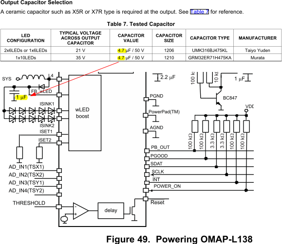
Although on page 66 the two recommended output capacitor have 4.7µF capacitor, on page 71 Figure 49.  Powering OMAP-L138, an output capacitor of 1µF is shown. Which should I follow?

Input capacitor

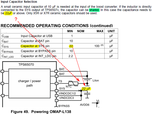
Page 66 suggest that a 22µF input capacitor might be shared when inductor is directly connected to SYS pin.

On page 3 Recommended Operating Conditions CSYS of minimum 22µF is recommended, which is also shown in Fig.49.

Does (1)'s inductor refer to the one in (2)?


Zheng

  • I suggest using the EVM components.  This is a working circuit that has been built and tested.  It will eliminate the need to work through the detailed calculations for all component values.

  • Anonymous
    0 Anonymous in reply to Matthew Day

    Michael,

    I missed the notification mail, sorry for my late reply.

    I just had a look at the EVM BML and I believe I should refer to it much earlier. Thanks for suggestion.


    There is another question with TPS6507x EVM. I checked the capacitors in the EVM and all of them are MLCC type. However, according to Use of MLCC Capacitors from Enpirion, a company specialized in power systems, MLCC capacitors lose a great portion of capacitance under two conditions:

    (1)  High frequency, like > 100KHz

    (2)  DC Bias voltage

    There measurement with network analyzer show that the larger and thicker the capacitor is, the less loss there would be under the two conditions.

    For 22µF capacitor, the 0805 type used in TPS6507x EVM BOM has been measured to become 12µF, or lose 33% or 55% capacitance under 3V and 5V DC biases.

    The date of this Enpirion article is in 2005. I have no knowledge on whether MLCC manufacturing technology has advanced during the six years so both (1) and (2) have been successfully addressed so far. But if there conclusion still remains valid, does that actually suggest some problem with the EVM?

    The same question also extends to virtually all other capacitors in EVM since most are MLCC. For example, for 4.7µF and 2.2µF capacitors, is there necessity to choose larger size, as Enpirion suggested?

    Or, perhaps that all the possible capacitance loss have already been considered by TI engineers when making capacitance recommendations and the recommended values in TPS6507x datasheet already admit capacitance change, so that I don't need to consider it twice?


    Tantalum

    In page 15 of LP2985 datasheet SLVS522N, tantalum capacitors are described as having higher ESR and it increases with temperature than ceramic counterparts. However, regarding the loss capacitance at condition (1) and (2), does the same also exist for tantalum capacitors?


    Zheng