This thread has been locked.

If you have a related question, please click the "Ask a related question" button in the top right corner. The newly created question will be automatically linked to this question.

UCC28600: Finding Rcs and Rpl value since it provides different equations

Genius 17365 points
Part Number: UCC28600

Tool/software:

Hi Experts,

Good day. Would like to ask assistance on design application and documentation for UCC2860 raised by customer below:

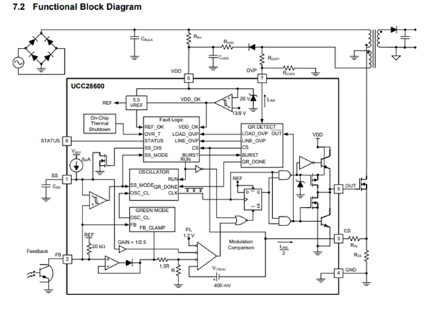
While finding Rcs and Rpl value of the UCC2860 ıc, the documentation has differenet equations. And they gives different value.

https://e2e.ti.com/support/power-management-group/power-management/f/power-management-forum/1450662/ucc28600-ucc28600-rcs-and-rpl-equations-mismatch-in-datasheet?keyMatch=ucc28600&tisearch=universal_search

in the support part there is a answer like that, but it is also not clear.

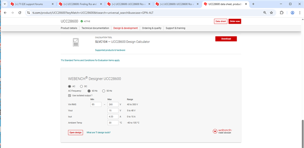
I am planning to use UCC28600 IC. but while designing ı cannot use slv104j calculator excell document because it is different than ıcs document. UCC28600 documnet is have 2 different equation about the determination of Rcs and Rpl resistors.

I am trying to use the sample document but my circuit has different specifications

it has 3phase 340-530Vac input and 12V2A 12V1A 12V1A isolated output and 15V0.2A auxilary. my efficiency will minimum 80% and I will use UCC28600 QR mode flyback convertor IC

I am planning to use 65khz switch frequency for my converter. I am using 1700V SiC mosfet and I dont want to use PFC unit. 

Thank you.

Regards,
Archie A.

  • Hello,


    Your inquiry will be reviewed in the order it was received.


    Regards,

  • Hello,


    The UCC28600 is an older device and sorry it is not clear.   If you use the excel tool and have a DC input you just need to multiply the min and max AC by (2)^0.5.

    The other option you have is the Webech design tool which can be found at the following page.

    https://www.ti.com/product/UCC28600?keyMatch=UCC28600&tisearch=universal_search&usecase=GPN-ALT

    You just enter the input and output power requirements and it will generate a BOM and schematic for you.


    I know what the RPL resistor is supposed to do and I am not exactly sure why they made it so cryptic in the data sheet for this device.  The RPL is just to remove offsets in peak current caused by the delay of the UCC28600 CS to output control.  The delay for this device is roughly 175 ns (td).  The offset the RPL resistor adds will cause the signal will cause the output to turnoff early to remove the error cause by td.


    You need to size your current sense resistor (Rcs) based on conventional methods using primary peak current.  The following equation can be used to size Rcs based on 80% of the power limit including the 0.4V offset inside the IC.  This is generally how I size Rcs in my designs. 

    Rcs = (1.2-0.4V)*0.8/(Transformer Primary Peak Current) = Rcs = 0.64V/(Transformer primary Peak Current)


    ROVP1 and ROVP2 are used for to detect OVP and ROVP2 is used to sense the line voltage.  ROVP2 is also used to produce a current ILine that is used to generate and offset across RPL (VRPL) when the FET is on.  This is to cause the FET to run off early to remove excessive primary peak current cause by IC delay.


    ILine = VBULKmin*(Na/(Np*ROVP1)


    VRPL = (ILine/2)*RPL

    I thing the easiest way to size the RPL resistor is based on the peak input voltage (Vin_max) and change of current caused by the IC delay (di) and the transformer primary magnetizing inductance (Lpm).

    di  =  Vin_max*dt/Lpm = Vin_max*175ns/Lpm

    Rpl = (di*Rcs) /(ILine/2)


    Regards,