This thread has been locked.

If you have a related question, please click the "Ask a related question" button in the top right corner. The newly created question will be automatically linked to this question.

TPS54386: TPS54386PWPR

Part Number: TPS54386
Other Parts Discussed in Thread: TPS54383

Tool/software:

Hello,

I am currently using the TPS54386PWPR dual synchronous buck converter in my design, which provides 3.3 V and 5 V outputs from a 12 V or 24 V input source. However, I am facing some design challenges and would like your guidance.

My updated design requirements are as follows:

  • Input Voltage: 12 V or 24 V nominal (expected range: 10 V to 26 V)

  • Outputs:

    • Channel 1: 5 V @ 2 A

    • Channel 2: 3.3 V @ 2 A

  • Application: Compact embedded system (industrial-grade)

  • Constraints:

    • Preference for a single-chip dual-output buck converter

    • Minimal external components

    • Cost-effective (with some flexibility on price)

In addition, I am experiencing difficulty selecting appropriate inductors for this device under my load and ripple current constraints. I’d appreciate your recommendations for inductor specs (current rating, saturation, ripple) or any validated inductor part numbers.

I would also be grateful for any reference designs, Webench simulations, or application notes that could help fine-tune my design.

Thank you for your support.

  • Hi Dhruvil, 

    Check with these parts: 

    TPS54286 data sheet, product information and support | TI.com

    TPS54294 data sheet, product information and support | TI.com (Cost economic)

    TPS54295 data sheet, product information and support | TI.com

    Our Webench tool itself recommends suitable components. Give it a try.

    Regards,
    Gautam

  • Hello Gautam,

    Thank you for your response and for suggesting alternative parts. However, for my project and layout constraints, I would like to continue using the TPS54386PWPR specifically, rather than migrating to other devices at this stage.

    As the TPS54386 is not available in the Webench tool, I kindly request your support in the following areas:

    1. Schematic reference/design guide for dual outputs of 5 V @ 2 A and 3.3 V @ 2 A from a 12 V/24 V input.

    2. Inductor selection guidance for both outputs — recommended values and part numbers that ensure reliable operation with minimized ripple current and acceptable saturation current (for both channels at 2 A load).

    3. Any validated BOM, application note, or reference design based on the TPS54386 that aligns with these specifications.

    This will help ensure that I can properly size the key passive components and finalize a robust design around TPS54386PWPR for my application.

    Thank you in advance for your continued support.

    Regards,
    Dhruvil

  • Schematic reference/design guide for dual outputs of 5 V @ 2 A and 3.3 V @ 2 A from a 12 V/24 V input.

    Please refer to figure 37 of Datasheet. 

    Inductor selection guidance for both outputs — recommended values and part numbers that ensure reliable operation with minimized ripple current and acceptable saturation current (for both channels at 2 A load).

    Section 9.2.1.2.2 Inductor Selection clearly describes the way to do it. Please refer the BOM to select inductor from the same series but lower current rating

    Any validated BOM, application note, or reference design based on the TPS54386 that aligns with these specifications.

    Your closest reference design would be https://www.ti.com/tool/TPS54386EVM. Refer to its BOM and Userguide. 

    Regards,

    Gautam

  • Hello Gautam,

    Thank you once again for your prompt response and for the useful references you provided earlier.

    I would like to inform you of a small update to my design requirements.
    We have now finalized the input voltage as 24 V (fixed).

    I will continue using the TPS54386PWPR part and kindly request your support specifically for:

    • Inductor selection guidance for both outputs (5 V @ 2 A and 3.3 V @ 2 A) from a 24 V input

    • Recommended inductor values and part numbers (ensuring reliable operation with minimized ripple current and acceptable saturation current for both outputs)

    • Please suggest a schematic design suitable for my application requirements (24 V input, 5 V/2 A and 3.3 V/2 A dual outputs)

    Your support on selecting the appropriate inductors and schematic design will greatly help in finalizing a robust solution.

    Thank you in advance for your continued guidance.

    Regards,
    Dhruvil


  • Hi Dhruvil,

    Please refer to equation 11 in DS for calculating inductor values. For schematic, you can refer to figure 37 in DS, you might need to update component values based on your application.

  • Hello Himanshu,

    I would like to clarify that in my application, I am using a fixed 24 V input voltage (not the 9.6 V to 13.2 V input shown in Figure 37 of the datasheet).
    I plan to generate dual outputs of 5 V @ 2 A and 3.3 V @ 2 A using the TPS54386PWPR.

    I have reviewed Equation 11 in the datasheet for inductor calculation, but I am facing difficulty understanding how to apply it properly for my specific case with a 24 V input.

    Therefore, I humbly request your support on the following:

    • Please suggest the recommended inductor values and part numbers for both outputs (5 V and 3.3 V at 2 A load, with 24 V input), ensuring minimized ripple current and acceptable saturation current

    • Please suggest recommended values and part numbers for the other key components (such as capacitors and resistors) based on my application

    • If possible, please share an appropriate schematic design reference aligned with my input and output conditions

    Your detailed guidance on inductor selection and overall design will be extremely helpful to finalize a robust and reliable design using TPS54386PWPR.

    Thank you in advance for your continued support.

    Regards,
    Dhruvil

  • Please define "minimized ripple current and acceptable saturation current". That is up to you to select

  • Hello Himanshu,

                To clarify my design intent:
                For both outputs (5V @ 2A and 3.3V @ 2A), I am targeting the following:

    • Inductor ripple current: 20% to 30% of output current, which corresponds to 0.4A to 0.6A (for 2A load current)

    • Acceptable saturation current of the inductor: at least 2.5A to 3A, ensuring it exceeds peak load current (2A + half ripple current

      Based on this, I kindly request your recommendations for:

      • Suitable inductor values and part numbers

      • Recommended capacitor and resistor values / part numbers (for stable operation)

      If possible, a schematic design reference aligned with my 24V input and dual-output requirement would be very helpful.

      Thank you again for your support.

      Best regards,
      Dhruvil

  • Please use XGL4040-153MEC, 2 x C2012X5R0J106M along with a bulk 150uF electrolytic capacitor


  • Hello Himanshu,

    I have a few follow-up questions and a request for design clarification:

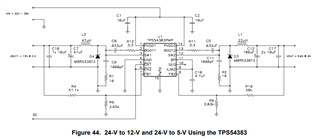
    In Figure 44 of the TPS54383/86 datasheet, the reference design shows 5V and 12V outputs, whereas my application requires 5V @ 2A and 3.3V @ 2A from a 24V input.

    • The 5V rail from the reference design suits my needs.

    • I kindly request your help in modifying the 12V rail to output 3.3V @ 2A.

    Could you please:

    1. Confirm whether the suggested XGL4040-153MEC (15 µH) inductor is for the 5V or 3.3V output?, and recommend an inductor for the other rail.

    2. Confirm the placement of the 2 × C2012X5R0J106M (10 µF, 6.3V, X5R) capacitors — are they for input bypass or output filtering?

    3. Advise where the 150 µF bulk electrolytic capacitor should be placed — input or output? Also, is a specific ESR requirement recommended?

    4. Suggest updated component values and part numbers (inductors, capacitors, resistors, diode, etc.) for the 3.3V @ 2A output.

    5. Provide a reference schematic (if available) for a 24V input, dual-output (5V/3.3V) configuration using TPS54386PWPR.

    Best regards,
    Dhruvil Bhadani

    • I kindly request your help in modifying the 12V rail to output 3.3V @ 2A. - All the components would work fine for 24V rail, provided you select the correct voltage rating

    • Confirm whether the suggested XGL4040-153MEC (15 µH) inductor is for the 5V or 3.3V output?, - Both

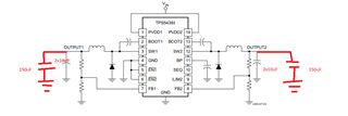
    • Confirm the placement of the 2 × C2012X5R0J106M (10 µF, 6.3V, X5R) capacitors — are they for input bypass or output filtering? - output filter

    • Advise where the 150 µF bulk electrolytic capacitor should be placed — input or output? Also, is a specific ESR requirement recommended? - after output filter

    • Suggest updated component values and part numbers (inductors, capacitors, resistors, diode, etc.) for the 3.3V @ 2A output. - can use same 

    • Provide a reference schematic (if available) for a 24V input, dual-output (5V/3.3V) configuration using TPS54386PWPR

  • Dear Himanshu,

    Thank you for your prompt response and clarification.

    I now understand that the XGL4040-153MEC (15 µH) inductor and the C2012X5R0J106M capacitors are suitable for both 5V and 3.3V outputs. However, I still have some doubts regarding the exact placement of these components, particularly:

    1. Should the 2 × 10 µF X5R and the 150 µF bulk electrolytic capacitor be placed at the input or output?

    2. Is there a specific ESR requirement for the 150 µF capacitor?

    3. Do I need to update the feedback resistor values when converting 12V to 3.3V @ 2A?

    4. If possible, could you share a hand-drawn circuit or block sketch indicating component placement for clarity?

      Best regards,
      Dhruvil Bhadani

    1. hould the 2 × 10 µF X5R and the 150 µF bulk electrolytic capacitor be placed at the input or output? - output

    2. Is there a specific ESR requirement for the 150 µF capacitor? - <50mohm

    3. Do I need to update the feedback resistor values when converting 12V to 3.3V @ 2A? - follow this equation  from sec 8.3.7 in DS

  • Dear Himanshu,

    Thank you for your continued support.

    PrayTo ensure correct layout, could you kindly share a simple hand-drawn or block diagram showing the recommended placement of the 2 × 10 µF X5R,150 µF bulk capacitor,50mohm capacitor and 15uH inductor, especially for a 3.3 V @ 2 A output from 24 V input using TPS54386PWPR?

    This would greatly help in avoiding any design errors.

    Best regards,
    Dhruvil Bhadhani

  • Hello Himanshu,
    Could you please recommend the appropriate component values (capacitors, resistors, inductor, etc.) for this configuration, especially for the 3.3V output rail?
    Best regards,
    Dhruvil Bhadhani

  • Please read the above comments for inductor and capacitor values. For FB resistor values, you can use 20kohm between vout and fb and 6.34kohm between FB and ground.