Tool/software:
Hello,
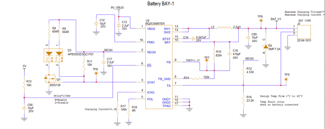
I have designed a custom Li-ion battery charger circuit using the BQ25306.
Charging Voltage=7.1V
Charging Current=0.3A
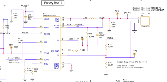
I'm encountering an issue with the BQ25306. When I connect a 6V battery to the J2 connector and power on the Vbus supply, the system functions correctly, and the battery charges as expected.
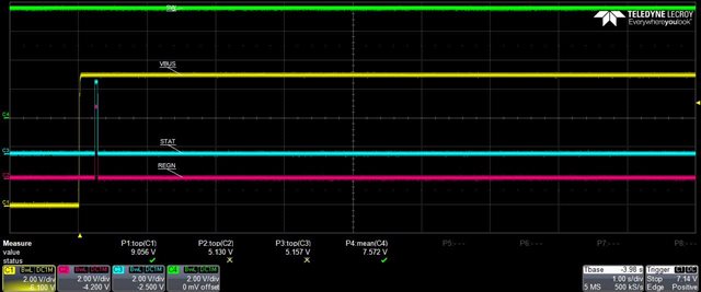
However, when I connect a 7.5V battery to the J2 connector and turn on the power supply, the REGN pin appears to short to the ground.
Could you provide any insights into what might be causing the REGN voltage to drop to zero in this scenario? Has anyone else experienced this issue?
I'm also wondering if we should avoid connecting a battery to the system if its voltage is higher than the intended charging voltage. It seems to work fine with a battery voltage below the charging voltage.
Any suggestions or guidance you could offer would be greatly appreciated.
Regards
Sabitha N