


Tool/software:
I recently had a circuit manufactured based around the TPS61200, designed to boost the voltage of a single cell rechargeable AAA battery (1.2v) to 3.3v for use in powering a single low current LED.
I have set the output resistors to provide a voltage of 3.3v, which the device achieves successfully, and the UVLO resistors are set to cut out at less than 0.9v input.
The load on this regulator is <1mA, however I measure a load on the input of 23mA irrespective of the external load on the 3.3v side of the circuit. This is a lot higher than the quiescent current of the device, and I cannot reconcile this high value with the efficiencies stated in the datasheet.
Have I made a mistake with the schematic, or is this expected behaviour?
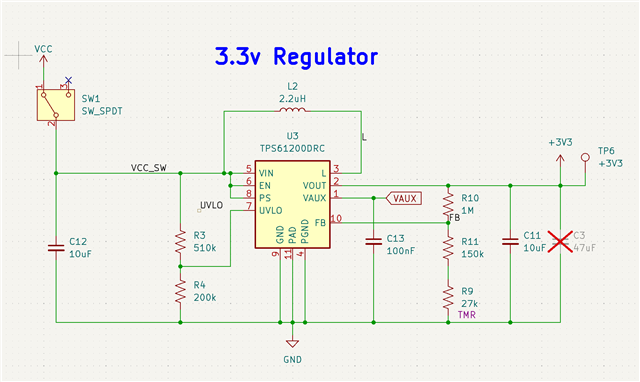
(Please note that I am using three resistors for the output regulation resistors to facilitate BOM consolidation.)

