This thread has been locked.

If you have a related question, please click the "Ask a related question" button in the top right corner. The newly created question will be automatically linked to this question.

TPS65988DK: CC pin misbehave when Device is connected on the CC lines

Part Number: TPS65988DK
Other Parts Discussed in Thread: TPS65988, TPS25751

Tool/software:

Hello Team,

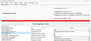
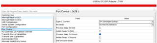
We are using TPS65988DK PD in our design .We are facing one issue with CC lines .

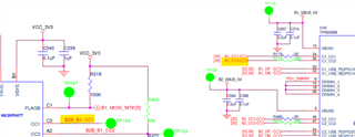
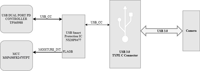
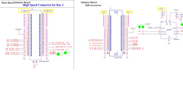
Please find arch block diagram, CC2 line is no mount , we are using only CC1 line for detection


NX20P0477 is the Moisture Sensor IC from NXP which detect moisture on the CC lines .

When the Device is connected on the type C connector (with no moisture ) the CC lines impedance goes low (voltage goes low approx 400mV to 300mV)
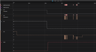
below waveform - measured on CC1 (IC input TP148)and FLAG (TP154 flag pin) in moisture fault condition.

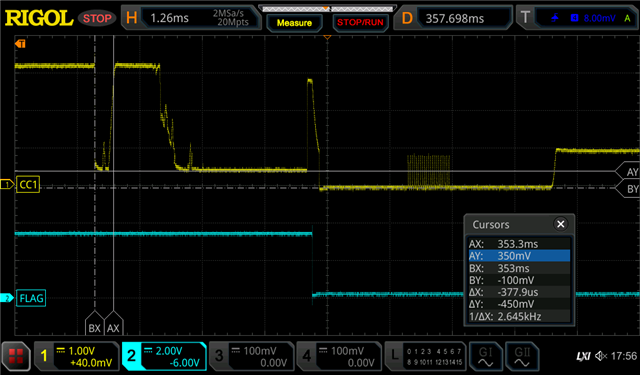
Observation: As seen in the image above, a 350mV drift was observed on the CC line under fault conditions, and a moisture fault occurred after 4.3ms


 below waveform - measured on CC1 (IC input TP148)and FLAG (TP154 flag pin) in charging condition


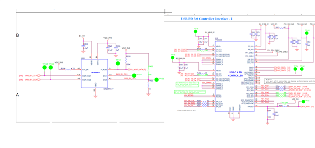
This is the Random Behaviour we are observing in our boards .Sometime the Moisture fault is generated and sometime not . Please check the waveform and schematic attached and suggest the possible solution .


  • Hello,

    What is the expected behavior of the CC line when a fault is detected?  

    The net names are different.  Does this mean there is additional circuitry between the nets?

    Please provide the expected theory of operation.  We provide the moisture detection in the TPS25751 (TPS65988 is not recommended for new designs) and this works with the PD functionality in an integrated and unified way.

    https://www.ti.com/lit/ds/symlink/tps25751.pdf#page=56

    Regards,

    Chris 

  • Hello Chris,

     Does this mean there is additional circuitry between the nets? -- There is B2B connector between the two IC,

    Expected behaviour of CC pin waveform shown below


    200mV to 300mV on CC line when fault is detected .

    I am sharing the NX20P0477datasheet for your reference : NX20P0477 (2).pdf

  • Hello,

    I cannot comment on the NXP device.  I would recommend using the TPS25751.

    Regards,

    Chris

  • Hi,

    Understood you can not provide NXP side data but can you please provide the USB PD side information. Whenever the communication will happed on CC pin what will be the PD side behavior ? Can you please share an waveforms. 

    Please let me know if any other extra configuration is required at PD side we are using the TPS65988DKRSHR part in our design. 

  • Hello,

    Understood you can not provide NXP side data but can you please provide the USB PD side information. Whenever the communication will happed on CC pin what will be the PD side behavior ?

    I do not understand.  In the waveforms you mention that the CC line is measured at TP148.  My understanding is that this is the CC line between the USBC connector and the NXP device and not the CC voltage at the TPS65988 device.  Please confirm.

    Please be advised that this device is "Not Recommended for New designs". https://www.ti.com/support-quality/quality-policies-procedures/product-life-cycle.html

    This device is certified by the USB-IF for PD3.0 which defines the behavior of the CC lines.  The voltage thresholds for source, sink, and active cable detection are found in section 6.8 of the datasheet.

    https://www.ti.com/lit/ds/symlink/tps65988.pdf#page=11

    Please let me know if any other extra configuration is required at PD side we are using the TPS65988DKRSHR part in our design. 

    Do you need to disable the PD until after the liquid detection has gone away?  What is your control mechanism to enable and disable the PD controller to account for this?  What are the expectations of the PD controller and how do you expect this to work?

    The source device will provide a pullup based upon the strength of the current advertisement.  The Sink will provide a constant pull down resistance.  The resulting voltage divider will alert the sink to the available current supplied by the source.

    Regards,

    Chris

  • Hi Chris,

    I wanted to share the flow for moisture detection with you. Please refer to the image below for more details.

    When moisture is detected on the slave side USB connector, the NX20P0477 IC senses it, triggering an interrupt that is sent to the MCU via GPIO. The MCU then disables the switcher, which cuts off the power to the Type-C VBUS.

    Additionally, in the past, we used the TPS65988DHRSHR, and it worked well with the NX20P0477 IC. However, following our previous discussion with TI, they recommended switching to the TPS65988DKRSHR PD. Now, we’re encountering issues with moisture detection. We’ve reached out to you to check if any additional software configuration might be needed at PD side to resolve this issue.

  • Hello,

    Can we restate the problem as this?

    With the TPS65988DH the product performs like this:


    Expected behaviour of CC pin waveform shown below

    With the TPS65988DK the product performs like this:

     below waveform - measured on CC1 (IC input TP148)and FLAG (TP154 flag pin) in charging condition

    The hypothesis is that the PD controller is somehow impacting the moisture detection device such that the CC waveform is different and the FLAG is never set in the moisture present test case.

    The difference between the TPS65988DK and the TPS65988DH is purely a firmware update.  The CC modem and the associated hardware peripherals are not changed.  

    In terms of the configuration settings, is the PD role set to DRP (dual role port) or is it a dedicated Sink or Source?  If it is a dedicated sink then there should be no difference in the Rd presented by the PD controller.  

    If DRP or source the Rp may change depending upon the current advertisement selected in the GUI.  

    Regards,

    Chris

  • Hi Chris

    Please find snaps nelow from ACT tool for what we configure in our PD configurations for DK part for both of the ports.

    (0x28) Port configs.

    Port control (0x29)

    Kindly suggest what changes we should do to avoid this detection issue.

    Thanks & Regards

    Nitish

  • Hello,

    How do these configurations compare with the DH part that worked?

    What is the intended role of the part?  Does it need to support DRP?  Can you test with SINK only or source only to see if that changes the behavior of the moisture detection device?

    Can you change the strength of the pull up resistor by decreasing the Type-C current to 1.5A or the default current.

    Regards,
    Chris

  • Hi

    The Intended role of the part is DFP (provides power delivery to the connected typeC device). It does not require DRP.

    We changed the strength of the pull-up to 1.5A and default current, but the moisture issue is still occurring.

    Regards

    nitish

  • Hello Nitish,

    Please let me know if there are any questions about the following waveforms:

    Order of operation:

    1. Connect port partner emulating the camera to the DUT 88DK (using project file provided).
    2. Disconnect
    3. Flip cable and reconnect (note communication is now on CC2)


    Zoom in on first connection:

    Zoom in on 2nd connection:


    Regards,
    Chris

  • Hello Chris,

    Thanks for sharing the Waveform ,

    So according to the Files provided by nitish , the CC pin configuration are correct in PD ?Waveform shows the  expected behaviour according to the configuration set in PD .Please help to clarify this   

    Please find below waveform with Vsys supply(3V3) on the NXP part

    1. Normal condition without moisture fault detection 


    2. In Fault Detection


    Observation : in both the cases the Vsys (3V3) is stable .


  • Hello,

    Can you confirm operation of your system when the cable is flipped?  IE the CC communication happens on CC1 vs CC2.  I do not believe that the PD will respond if the VBUS is applied but there is no CC connection.

    Can you also comment on the difference between B1_5V and B1_VBUS_5V?  B1_5V is connected to VBUS of the protection device and PPHV of the PD controller.   I would have expected both VBUS of the PD and the protection device to be connected to the USB-C connector VBUS.

    Regards,
    Chris

  • Hello Chris ,

    Our Camera Device has the type C receptacle and the Dock Board (which Contains the PD ) has the type-c Plug ,

    So when the camera is flipped Either CC1 or CC2 will be the connected to the CC pin net name USB_B1_CC1 (A5 pin) of the plug (Dock Board ).

    Please note in Type-C plug B5 pin which has net name USB_B1_CC2  is dummy .

    Camera Device Type-C Receptacle 


    Dock Board (Which has PD) Type C Plug


    Regarding VBUS, Basically there are two Board in DOCK 
    1. Main Board 
    2. Adaptor Board 

    Both Board are connected with B2B connector 

    PD is in main board and output of PD is B1_VBUS_5V , this net goes to B2B Connector
    But the Net name get change to B1_5V in the Adaptor Board B2B Connector NXP Protection IC is in Adaptor board  , So basically PD output supply is going to adaptor Board and NXP protection IC just net name get chnaged


    Hope this clear your doubt .

    Regarding the waveform your share ,please let me know those waveform are generated from the file which is shared by nitish ,
    Are those waveform have expected behaviour . Just wanted to know the PD setting are correct or not 

  • Hello,

    Yes. I can confirm the waveform was generated after receiving file shared by Nitish.  This waveform is expected.  You should be able to confirm the same on your side by bypassing the liquid detection device.

    Regards,

    Chris