This thread has been locked.

If you have a related question, please click the "Ask a related question" button in the top right corner. The newly created question will be automatically linked to this question.

LM5164: EN/UVLO and VIN Pin Damage Upon Power-Up

Part Number: LM5164

Tool/software:

Hi,

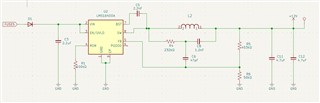
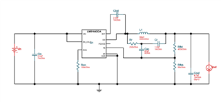
I designed a DC/DC buck converter using the LM5164DDAR IC with the help of WEBENCH. My target input range is 15–72V, and the output is 12V/1A. I implemented the circuit exactly as provided by WEBENCH and verified it against the datasheet recommendations.

However, I am facing a critical issue: when the system is powered up (around 58V input), a burn or explosion occurs at the VIN and EN/UVLO pins of the IC.
Below, I have attached the schematic and photos of the damaged IC for your reference.

I would appreciate your support in identifying the cause of this issue.

  • Hello Selim,

    Looks like electrical over - stress.  Do you have a damped input supply?   if you have long cables or an input filter, you will need to use a damping cap in parallel with C3.

    If you need further assistance, please fill out calculator spreadsheet with you requirements and post so I can check your schematic against the recommended values.  If that checks out, its likely a layout issue, did you follow the layout guidelines closely in the datasheet, check your layout against the EVM layout and or the guidelines we have provided.

    Hope this helps,

    David.

  • Hi David, thank you for your response. Yes, I followed the layout guidelines carefully, especially those in the datasheet. The design I implemented was created using Webench. I will be heading to the lab shortly and will add a 100nF damping capacitor in parallel. I’ll share the results afterward.

  • Hi David,
    I believe the issue was due to the long input cable I was using. After shortening the cable as much as possible and running some tests, the circuit worked without any problems. However, when I tested the same circuit again with the cable extended, it failed after a few attempts. This is most likely the root cause.
    Now I’d like to add a damping capacitor. Could you advise me on how I should implement it in the circuit?

  • Hello Salim,

    Yes, the Damping cap needs to be at least 4 times larger that the capacitor that is is damping.  for example, if you have a 10uF ceramic input cap, then you will need to use a 47uF damping capacitance.  the Resistance is the damping resistance that can be a physical resistor, or the ESR of the damping capacitor, this typically needs to be ~0.5ohm to 10ohm resistance. 

    Hope this helps,

    David.

  • Hello again, David.
    Yes, adding the damping capacitor solved my issue. I initially had only a 2.2 µF input capacitor. I added a 33 µF electrolytic capacitor, along with 2.2 µF and 0.1 µF capacitors in parallel to it. This solution is working for now. Thank you for your support.