This thread has been locked.

If you have a related question, please click the "Ask a related question" button in the top right corner. The newly created question will be automatically linked to this question.

BQ40Z50-R2: Strange RSOC / ASOC values, remaining capacity and full charge capacity looks weird

Part Number: BQ40Z50-R2
Other Parts Discussed in Thread: GPCRA0

Tool/software:

Hi,

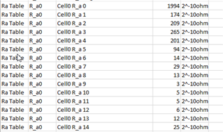
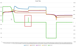
This is a 4S5P LFP pack with the capacity of 8AH. The cells has been characterized by TI, they have ChemID4207
The learning cycle was finished, the update status is 0E. But the capacity values seems bad.


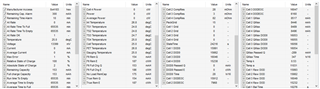
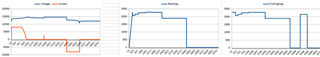
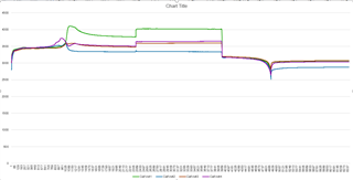
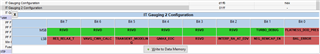
Please see the config and the attached log of a full charge-up.

strange_capacity.xlsx

Strange_Rsoc.gg.csv

  • Hello Kovacs,

    This question has been assigned and will be reviewed when possible.

    Thank you,
    Alan

  • Hi Kovacs,

    Based on the .gg file, it seems like the Ra_0 point in all of the Ra Tables is significantly higher than the rest. Is it possible to run the GPCRA0 test and share the results with us so we can confirm the resistance table values?

    https://www.ti.com/tool/GPCRA0 

    Regards,

    Anthony

  • Hi Anthony,

    Thanks for your answer!

    I seem to have forgotten that the config file does not contain the ChemID... When I was working on this pack I only loaded the config, I did not set the ChemID. Since then I have done the learning cycle resistance mapping with the correct ChemID and now the RA table values ​​are quite close to each other.


    However, the "Full Chg" values ​​still do not show the real value, even though the "Q and E" values ​​change according to charging and discharging.

    What do you suggest I do next?

    full_cylce.xlsx
    Strange_Rsoc2.gg.csv

  • Somebody spotted something wrong in the config file?

  • Hi Kovacs,

    It seems like the cell voltages variate a lot throughout this log file. Can you please confirm that cell balancing is enabled here?

    Regards,

    Anthony

  • Hi Anthony,

    Good catch, CB was not working. With an external balancing circuit, both CB, CBM and CBR bits are high. But it seems like the update status did not progressed from 06 to 0e and that's preventing the cell balancing. o.O That's a behavior I did not seen yet, usually when a learning cycle reaches the state of 06, it soon changes to 0e.

    Not sure how to proceed.


  • Hi Kovacs,

    The update status should change from 06 to 0E if another Qmax update occurs, which requires another cycle. Can you please confirm whether this has occurred?

    Regards,

    Anthony

  • Hi Anthony,

    It did not changed to 0E. What I tried:

    Discharge -> Rest -> Charge -> Rest -> Discharge -> Rest

    It did not worked, so I issued a reset command, and repeated this cycle. Still, update status is 06.

    Should I start the whole learning cycle from the begining? Can you please take a look on my config file? Maybe you spot something I missed.

    Regards,
    Tamas

  • Hello Tamas,

    We will continue to work on your question, today is a national holiday, Memorial Day.

    Thank you,
    Alan

  • Hi Kovacs,

    Looking into the log file, it looks like the cell voltage in during the relax period will enter the flat region, which will invalidate the Qmax update. For the chemID in use, this is around 3465mV. Also, can you please confirm the current spike during the middle of the charge?

    Regards,

    Anthony

  • Hi Anthony,

    Yes, I'm aware of the flat region voltage, it caused issues for the learning cycle in the past. In the chemistry file, both the low and high limit is 3465mV. Is this means a very narrow flat voltage region? During the learning cycles, this sometimes prevented to progress from update status 04 to 05 due to not doing the qmax update. To combat this, I disabled OCVFR bit in IT Gauging register. Maybe that was a mistake by my side?


    About the current spike in the charged state, this is something new... I fail to see a reason why the charge FET turned on when the pack was fully charged. The cell voltages was higher than the TC/FC recovery voltage. Based on the register values, I don't see any reason that could alter the state of the fully charged pack.

    Br,
    Tamas

  • Hello Kovacs,

    We have received your update and due to a back log of the queue we ask for some more time until we send a response.

    Thank you,
    Alan

  • Hi Kovacs,

    Yes, I'm aware of the flat region voltage, it caused issues for the learning cycle in the past. In the chemistry file, both the low and high limit is 3465mV. Is this means a very narrow flat voltage region? During the learning cycles, this sometimes prevented to progress from update status 04 to 05 due to not doing the qmax update. To combat this, I disabled OCVFR bit in IT Gauging register. Maybe that was a mistake by my side?

    I would not disable this option. It is important for the gauging algorithm that OCV measurements are not taken within the flat region.


    About the current spike in the charged state, this is something new... I fail to see a reason why the charge FET turned on when the pack was fully charged. The cell voltages was higher than the TC/FC recovery voltage. Based on the register values, I don't see any reason that could alter the state of the fully charged pack.

    The FC and TC bits will not disable the CHG FET unless the FET Options[CHGFET] = 1 and there is a [TCA] flag set at this time, so it is possible for the device to activate the CHG FET if enough charge current is seen.

    Regards,

    Anthony

  • Hi Anthony,

    Okay, I will enable the OCVFR bit and re-try the learning cycle. I have 3 spare battery packs to experiment with.

    About the normally hidden IT Gauging 2 Configuration, I have this register visible where QMAX_EOC is set by default. Afaik this can help the gauge to work with LFP chemistry. Is this okay?

     Br,
    Tamas

  • Hi Kovacs,

    I would leave this parameter default. Is the LFP_RELAX bit in the IT Gauging Configuration register set at this time?

    Regards,

    Anthony

  • I belive I did not changed any register in IT Gauging2. As far as I can remember, QMAX_EOC was set automaticaly because of the selection of an LFP chemistry.
    It is the default setting, or should I revert the whole application to hide IT Gauging2?


    Yes, LFP_RELAX is set in IT Gauging.

    BR,
    Tamas

  • To prevent possible issues, I re-started the learning-cycle today on all 3 packs, but with the gauges updated to 2.11 firmware. So the config is clean, the packs are individually calibrated for both voltage and current. Now there is no IT Gauging2, and IT Gauging is on default (LFP_RELAX is '1').
    Hope this solves the problems.

    v211_learning_ready.gg.csv

  • Hello Kovacs,

    We have received your update and we will be following up with you.

    Thank you,
    Alan

  • Hi Kovacs,

    Thank you for the update, I agree in the sense that if the register was previously hidden it should be left as default at this time. Please share the log files when available.

    Regards,

    Anthony

  • Hi Anthony,

    We are working on it... I had to swap the cells with factory new ones because of the jumpy nature of the LFP chemistry, some of the old ones reached the COV limit during the learning cycle... The new ones does not.

    Currently we have problems with the resistance update part of the learning cycle, it seems like C/5 or C/6 discharge is not good for this chemistry. We are trying C/9..C/10 discharge rate but it will take some time.

    Regards,
    Tamas

  • Hi Kovacs,

    Thanks for the update. Please be careful using a discharge rate close to C/10, since anything lower than this will not result in resistance updates and fail the learning cycle.

    Regards,

    Anthony

  • Hi Anthony,

    We are still trying to finish a proper learning cycle. As you suggested, we kept the OCVFR bit ON in the config. As the result, the QMAX readings takes more than 2 days to finish. During this time, the cell voltages slowly goes down to 3330mV.

    I had to decrease the charge voltage from 14.6V to 14.4V because otherwise at the very end of a charging the voltage of some cells briefly reached more than 4.1V and the QMAX measurement failed... With 14.4V charging all of the cells stayed below 3.9V. I don't know if it is normal with this LFP chemistry but I had seen this behavior with multiple battery packs using these cells.

    Other than the QMAX part, we also struggle with the resistance update part. It seems like discharge with C/10 (800mA) does nothing, and C/9 (890mA) did only changed some R_a params for one cell group.
    Prior I used C/5 or C/6 values but they resulted inconsistent values. For the next learning cycle I'm thinking about using 1 or 1.1A current.

    Br,
    Borisz