This thread has been locked.

If you have a related question, please click the "Ask a related question" button in the top right corner. The newly created question will be automatically linked to this question.

LM3478Q-Q1: soft start time

Part Number: LM3478Q-Q1

Tool/software:

Hi team, 

LM3478Q-Q1 has internal soft start control and 4ms typ value in datasheet. But customer found that the soft start time is changing along with VIN. The lower VIN the higher soft start rising time. May I know if it is aligned with device behavior and why? 

RFA=91K 

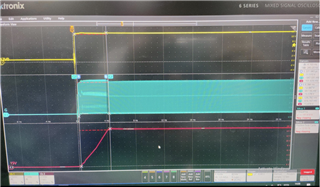
VIN=12V, soft start rising time=~4ms

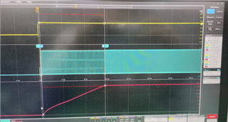
VIN=6.7V, soft start rising time=~11.48ms

Thanks!

Ethan Wen

  • Hi Ethan,

    Thanks for using the e2e forum.
    You are correct that the typical softstart time is fixed to 4ms.
    However, when starting the device at lower VIN, it can be possible that the output target voltage is not fully reached even though the softstart timer has already finished.
    This can happen either when the device operation with high duty cycle and needs more time to charge the output, or if the device is triggering overcurrent protection, which limits the duty cycle. The output can still come up during the overcurrent protection state, but as the duty cycle is limited, it takes longer.

    Please let me know if further explanations are required.

    Best regards,
    Niklas

  • Hi Niklas, 

    Thanks for your explanation. 

    How can we match the behavior shown from waveform with your explanation? Could you please help provide more details? How low the VIN will have this possibility? How high the duty cycle will need more time to charge output? 

    Regards,

    Ethan Wen

  • Hi Ethan,

    The engineer is out of office today. Please expect a delayed reply.

    Best Regards,
    Feng

  • Hi Ethan,

    The prove that the explanation matches with the measurements customer sees, I would need additional measurements from them.
    Could they zoom in into the timeframe of the softstart, that the duty cycle can be clearly seen on the switch node (or DR signal)?
    Additionally, they would need to measure the ISEN pin voltage, which is responsible for triggering the overcurrent protection.

    If they would be willing to share their schematic and the parameters for VIN, VOUT and ILOAD, this would be helpful as well.

    Best regards,
    Niklas