


Other Parts Discussed in Thread: TPL7407LA
Tool/software:
Hi all.
I am designing a board that will be required to switch on many relays, hence I am using TPL9202 to do the work.
I have validated the psuedo-circuit on a single TPL9202 on a breakout board and it works as intended.
When I put the circuit into the PCB, I have added more TPL9202 that is parallel on the SPI CLK and MOSI signal. However, I am not able to get the current sink on the output side when I am using the same code as in the pseudo-circuit.
Below is the simplified circuit on my board that involved the TPL9202.
On the RP Pi side, GPIO2 is defined as CLK and GPIO3 as MOSI. GPIO6 and GPIO8 is used as CS which will be handle in the code shown later.
All of the OUTX pin is connected to other relays in the same way shown below, I didnt include them here for simplicity purpose.

I am using a Raspberry Pi Pico 2 as MCU, and code is based on Thonny MicroPython.
Code as shown below.
The intention is just to light up some relays and see if the circuit is working.
So based on this code, I will expect RELAY1 to turn on and off; however, it's not.
from machine import Pin, SPI
from time import sleep,  sleep_us

u14 = Pin(5, Pin.OUT)
u14.value(1)

msg = bytearray()

# Initialize SPI
spi = SPI(0, baudrate=4000000, polarity=0, bits = 8, firstbit = SPI.MSB, phase=0, sck=Pin(2), mosi=Pin(3), miso=Pin(4))

while True:
    print(SPI(0))

    #sleep(10)

    print('Send out command')
    u14.value(0)
    sleep_us(1)
    spi.write(b'\x01')
    sleep_us(1)
    u14.value(1)
    print('Done send command')
    sleep(2)

    print('Send out command')
    u14.value(0)
    sleep_us(1)
    spi.write(b'\x02')
    sleep_us(1)
    u14.value(1)
    print('Done send command')
    sleep(2)
I have probed the CS, CLK and MOSI pin, all the waveform seems normal to me. I am happy to provide the snapshot of the waveform if that helps.
I also have tried some other things that do not work as summarized below:
- Change the TPL9202. I have verified good units from the breakout board and then swap to the designed PCB and it will not work.
- I have desoldered all but left one TPL9202 in the PCB, in case it was the SPI paralleling causing the problem. Do not work.
- Noticed that the breakout board do not have a ground pad, I also tried to isolate the ground pad on the PCB. Do not work
- Changed the code to different baud rate. Do not work.
- Changed polarity to 1 and phase to 1. Do not work.
- Removed the delay after CS pin pulled down. Do not work.
*The breakout board mentioned looks like the picture below.
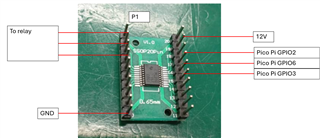
Basically, it is the same as the PCB circuit connection but without a ground pad connection and the decoupling cap at the VIN.
I feel like I have done something wrong, whether it's the circuit side or programming side, but I am not able to figure out how.
Can anyone please help to advise me?
Thank you for the time.
