This thread has been locked.

If you have a related question, please click the "Ask a related question" button in the top right corner. The newly created question will be automatically linked to this question.

TPS7A4701-EP: Support for dual power supply

Part Number: TPS7A4701-EP

Tool/software:

Hi,

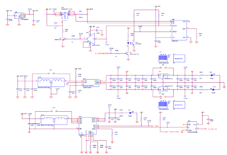
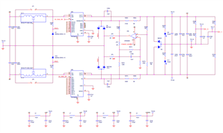
I need support for dual symmetric power supply design using TPS7A4701 and TPS7A3301.

Input voltages are +/-8V and output voltages must be +/-5V.

Attached you can find semplified TINA circuit simulation and it seems to be right. We produced PCB but during debug we see +6.5V/-0.8V.

In the PCB we used single OPA992S.

If necessary we can share electric schematic.

Can you support us to understand where is problem, in the simulation or in the PCB.

Best Regards.Dual Tracking Power Supply.TSC

  • Hey,

    Can you please share the electrical schematic?

    Thanks,

    Vahnroy

  • Hi Vahnroy,

    below the schematics.

    After start-up we measure +6.5V/+0.8V and not +5V/-5V. After some seconds power supply turn off, it seems by current protection on 28V, probably because there is something that causes the card to absorb extra power, perhaps the unbalance of the outputs... in any case the card turns off... at that point I turn the card off and on again and everything starts again but always with +6.5V/+0.8V and after a while it turns off. It is also strange that the protection intervenes because the R287 resistor is 15K and in any case the +28V power supply is limited in current to about 600mA.

    Thanks for support.

  • Hey,

    We're not seeing anything that would case this issue from what you have shared. Here are some things to try and narrow down the issue.

    Can you please share a scope shot of the op-amp out, 5v, and -5v rail during startup. 

    If you haven't tried already disable the op-amp, populate JP2 and JP4 to ensure the regulators are regulating properly.

    The startup for TPS7A033 is greater than a second with your NR/SS value. Is this intended?

    Is there any particular reason you need the balance of the outputs?

    Can you clarify the voltages you're seeing on the outputs?

    Thanks,

    Vahnroy

  • Hi Vahnroy,

    problem solved... D12 is not correct (bad configuration) and D12 is correct in the schematic but the p/n mounted is BAS40-06-7-F and not BAS40-04-7-F.

    For D12 now we have used BAT54s component appropriately adapted, and not BAT54A.

    Currently we no longer have the problem of current absorption but another strange situation occurs... practically without U64 circuit the voltages are +5/-5V approximately while using U64 we have +4.9V/-5.2V... practically there is no balancing effect.

    Do you have any ideas about this?

    Thanks for your support.

  • Hi Vahnroy,

    have you had the chance to analyze the problem? Please, let me know.

    Thanks for your support.