This thread has been locked.

If you have a related question, please click the "Ask a related question" button in the top right corner. The newly created question will be automatically linked to this question.

UCC256404: UCC256404 no output regulation in startup

Part Number: UCC256404

Tool/software:

Hello. Can you give me any idea, what causes that output is not regulated to desired value. I used new trafo for higher power with, device is UCC256404. Calculations are included.  Desired output value is 80V. After power on, output value increases from 0 to 96V, then is stopped with BW (which is set to overvoltage has 120%).  It is ever 1 sec. The same with and without load (1A) System is designed for 80V and 8A.

Feedback is type 3. 

Here is Vout 1:10 in starting.

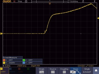
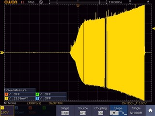
Output from transformer 1:10


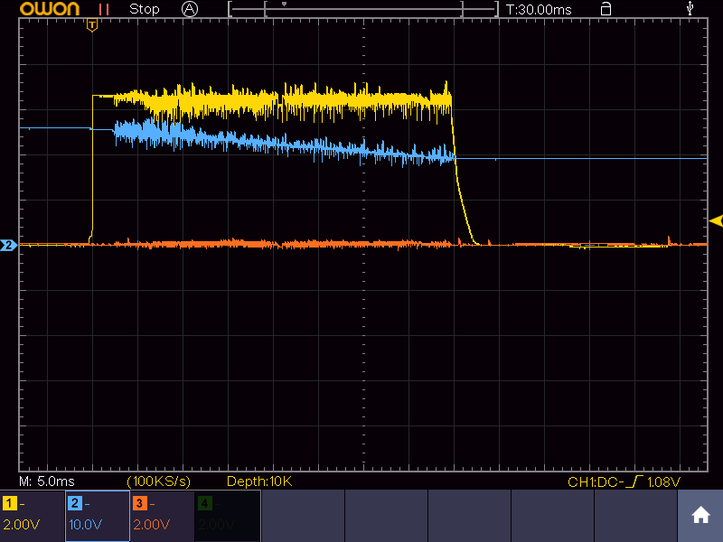
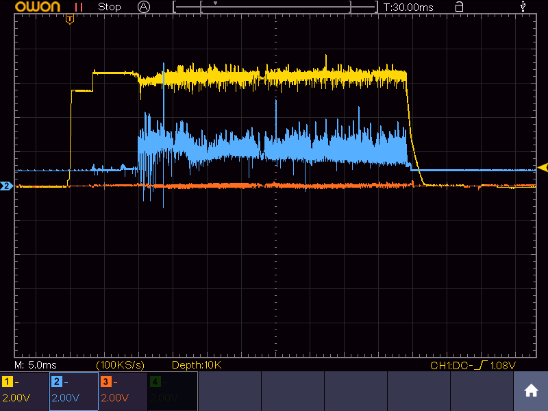
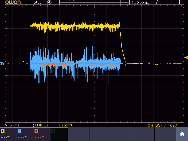
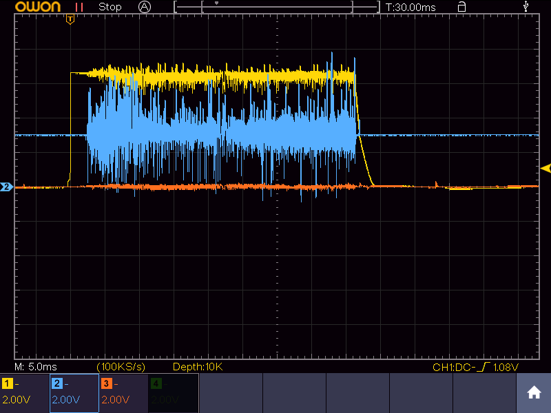
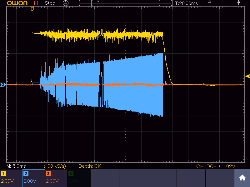
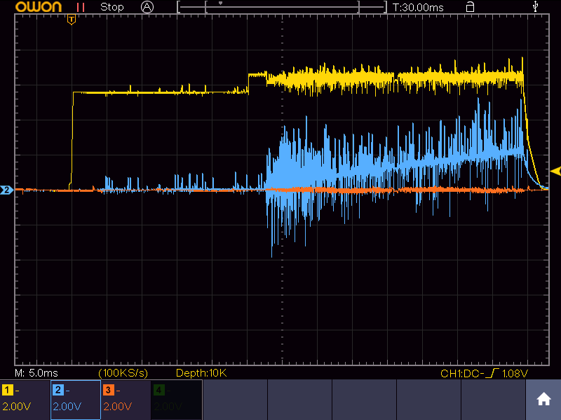
Here is combined view of FB (yellow), RVCC (blue), BW (red).
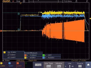
Detail of signals:

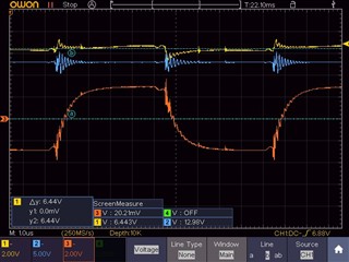
I think that FB may be in voltage 5.6-5.8 V, but is about 6.4V .

Optocoupler output is connected to FB, it's connected too to 6.8V zener anode, cathode is over 10k resistor connected to RVCC. I also tried to change 6.8V zener to 7.2 zener, without effect, I removed zener diode, no effect. Output is still no regulated to 80V, and switched off in 96 V output (with BW overvoltage).

I tried to set resonant inductor to +-20 % of calculated value too.

System restarts every 1sec. Similar outputs without and with load too. Where to look for problem ? 

UCC25640x Design calculation 80V_8A_primary_160u_new_32_wings_100khz.xlsx

  • Hello,


    Your waveform looks like the design is shutting down do to some kind of fault causing VDD to cycle.  It could be shutting down due to over current, and/or input or output over voltage.

    To figure out which fault you will have to probe BLK, BW, ISN and VCC.  Look at the last three or four switching cycles before VCC discharges.  From these waveforms you should be able to determine which fault is causing the design to shut down.

    I reviewed the excel tool and did not see anything out of the ordinary.  Do you have a schematic that I could review?


    Regards,

  • scheme is the same as in evaluation board https://www.ti.com/lit/ug/sluubx3b/sluubx3b.pdf . Added only resonant coil, and change of resistors/capacitors from calculation (in excel above text.) Output is 80V, trafo ETD393 3f3. Feedback is in attached pdf file. feedback.pdf

    Here are signals:

    channel 3 (red) is not connected in all measurements.

    FB (yellow) VCC (blue)

    FB (yellow) BLK (blue)

    FB (yellow) ISNS (blue)

    FB (yellow) VCR (blue)

    FB (yellow) BW (blue)

    FB (yellow) RVCC (blue)

    FB (yellow) LL/SS (blue)

    I think all signals are in right range. 

  • Hello,


    Your inquiry will be reviewed in the order it was received.


    Regards,

  • Hello,


    Your FB pin and bulk pin seem to have a lot of high frequency noise on them.  These pins should not be that noise.  Maybe you have noise coupling into these pins.  You might want to retake these waveforms with the scope probe ground close to the UCC256404 IC ground.  Please note that noise on the BLK pin could trip OVP. 


    The ISNS pin also does not have enough resolution and seems to have a lot of noise on it.   You might want to retake the waveforms with the scope probe grounds close to the UCC256404 IC ground.


    One other thing you may want to decrease the time per division so you can look at the last 4 to 8 switching cycles before switching stops this will help in the debug process.


    I do have one last thought.  I wonder if you a biasing problem.  Could you bias the VDD with a separate bias supply?  You will just need to add a diode in between the bias and VDD.  If when power with separate bias supply it regulates you know the issue is due to biasing.


    Regards,

  • I found problem in feedback. In output from FB you can see that voltage is over 6 Volts, and may be about 5.6 Volts. Problem has been in feedback. 12V zener, which is in my design,  has been soldered with bad zener voltage, There was 6.8V zener  instead of 12V. It decreases current oved optocoupler diode. Now it works well. Stupid mistake from pcb supplier.

  • Hello,


    The inquiries will be evaluated in the order they have been received.


    Regards,

  • Hello,


    Thanks for letting us know that your issue was resolve.  I was glad that we could help.


    Regards,