This thread has been locked.

If you have a related question, please click the "Ask a related question" button in the top right corner. The newly created question will be automatically linked to this question.

TPS610981: Output Fluctuation on V-Main Under Light Load Conditions

Part Number: TPS610981
Other Parts Discussed in Thread: TPS61299

Tool/software:

I am currently evaluating an issue related to the TPS610981.
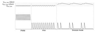
It appears that when the load becomes lighter than a certain threshold, the V-main waveform begins to fluctuate.
Could this behavior be caused by the light load condition?
If so, how much additional load would be required to stabilize the output?
Please refer to the attached PDF for further details.

This issue has only recently surfaced and does not occur on all PCBAs. It seems that only a small percentage of boards—likely a few percent—are affected.
Furthermore, this behavior was not observed during the initial design and evaluation phases, but has been confirmed in recent production batches.

A key question is why this phenomenon occurs only on some PCBAs, despite all units being manufactured under the same conditions.

Vmain waveform.pdf

  • Hi ,

    Is there any other difference between the two board , such as inductor and output capacitance. Could you also test the inductor waveform and SW node ?

  • Thank you for your response.

    As far as we can confirm, there is no difference in component values between the boards, including the inductor and output capacitance. Both use the same BOM and were assembled under the same conditions.
    The inductor is specified as 4.7 µH ±20%, and the output capacitor is 20 µF.

    The power source is two AA alkaline batteries in series.
    This issue occurs when the batteries are new and provide approximately 3.1 V in series. However, the issue does not occur once the voltage drops slightly below around 3.0 V due to battery usage.

    We have measured the inductor current waveform and the SW node as you suggested. The results are attached for your reference.

    Please let us know if you would like us to perform any additional measurements or tests.
    current.pdf

  • From my point of view, there is almost no difference between the two boards . Is this occasionally on the PCB? what is the percentage?

  • Yes, there doesn’t appear to be any significant difference in the inductor current waveform.
    However, there is a noticeable difference in the output voltage noise (ripple).
    Could this be related to operation in DCM mode?

    Out of 20 boards tested, approximately half show increased noise when the input voltage is above around 3.1 V.

  • Because from the waveform I don't see much operating difference except for the Vout ripple. Could you apply for the FA , customer return process, CQE process?

  • Before requesting an FA just to be sure, could you please let me know the conditions under which the IC enters DCM (Discontinuous Mode)?

  • Typically the load current smaller than 5mA.

  • Thank you very much for you support.

    May I ask two additional questions?

    1. What is the difference between DCM (Discontinuous Conduction Mode) and Burst Mode?

    2. Could you please explain the conditions under which the device switches between Normal Mode and Burst Mode?

  • Hi Yasuto,

    You could refer to this figure to distinguish between  DCM( the same with PFM mode ), burst mode and normal continous switching mode.

    For detailed description, you could refer to TPS61299 data sheet section 7.3.1, which is much more readible and easy to understand.