This thread has been locked.

If you have a related question, please click the "Ask a related question" button in the top right corner. The newly created question will be automatically linked to this question.

TPS65219: AM62 with TPS6521903 power on issue

Part Number: TPS65219
Other Parts Discussed in Thread: TPS6519,

Tool/software:

Dear Support Team,

We have designed a custom board using the AM62 processor along with the PMIC TPS6521903.
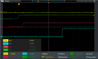
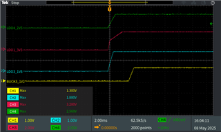
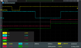
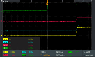
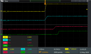
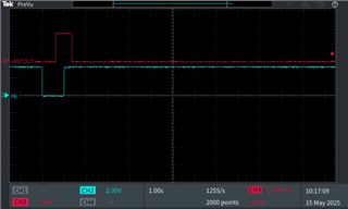
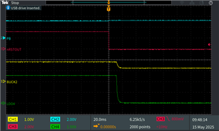
After powering on the board, we observed that the PMIC outputs the expected voltages correctly, but approximately 8 seconds later, the system shuts down unexpectedly.

Please find below the measured waveforms and the relevant portion of our power circuit design for your reference.

Could you kindly help us identify possible causes for this behavior?

We would appreciate your support and guidance on this issue.

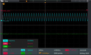
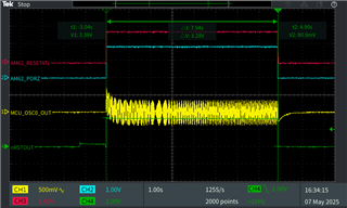
1. MCU_OSC0_XO 25Mhz

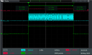
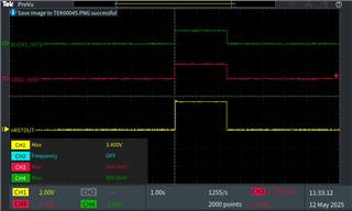
2. nRSTOUT pull high after MCU_OSC starts oscillating.

3.  Power off after around 8s

IEC-N241_PMIC_Power ON_issue_A03_0_0_20250317.pdf

Best regards,

Woody.

  • Hi Support Team,

    After measuring the PMIC power-up sequence, we found that the initial GPIO2 signal did not go high, which resulted in no output from the external DVDD_3V3 rail.
    We suspect this may be the reason why the PMIC shuts down approximately 8 seconds after power-on.

    Could you please advise if there is any specific configuration required for GPIO2?

    1. At initial power-up, GPIO2 never asserted (remained low).

    2. GPIO2 remained low even after the PMIC completed its full power-up sequence.

    Best regards,

    Woody.

  • Hi Woody,

    Thank you for reaching out on e2e and choosing TPS6519 for your power solution.

    yes, we need to check why GPIO2 is not coming up, is the pullup R426 okay?

    I reviewed the schematic and looked at the cap on Buck LX nodes, what is the purpose, these should not be present. Can you remove them (both 10u & 0.1u) and check again?

    Sathish

  • Hi Sathish,

    Thanks for getting back to us.

    We’ve checked the pull-up resistor R426, and it appears to be fine.
    We also tried removing the 10uF and 0.1uF capacitors on the LX line (C328–C333), but unfortunately, GPIO2 still doesn’t come up.

    In addition, we replaced the PMIC on the new board with one from the old version. After the replacement, GPIO2 started functioning normally, but it still shuts down after 8 seconds.
    Below is the waveform we measured after replacing the PMIC for your reference.

    We also noticed a difference in the PMIC markings:
    – The older versions are labeled P219XX or P21903
    – The newer one is marked 65219
    Could you please clarify if there’s any difference between these versions?

    Looking forward to your input.

    Best regards,
    Woody

  • Hi Woody,

    We can try couple of things.

    When you replaced TPS65219 PMIC, did you notice the powerpad solderdown to the PCB? This is compulsory.

    If you have access to read PMIC I2C to registers, can you please read registers 0x2B to 0x32 to know what is causing the PMIC to shutdown?

    One more thing, 8s corresponds to tPB_OFF. For TPS6521903 EN/PB/VSENSE pin is configured as PB but schematic shows it as EN. What is the status of PB pin on the board? Since FSD (First Supply Detection) is enabled on this 03 version of the device, it will ignore EB/PB during first power up only and as soon as VSYS reaches the necessary voltage the device will continue power up routine.

    Sathish

  • Hi Sathish,

    Previous GPIO2 Issue:

    The previous issue with GPIO2 was confirmed to be caused by a soldering defect. After testing three other PCB samples, GPIO2 was found to be functioning normally.

    • PMIC Self-Shutdown Issue – Two Scenarios Identified:

      • FSD Mode:
        In the original setup using FSD mode, the PMIC shut down about 8 seconds after power-on. Per your suggestion, we checked the EN/PB/ VSENSE pin and found them to be always low. After setting all three to always high, the PMIC operated normally and the AM62 booted successfully.

      • PB Mode:
        After verifying that FSD mode works correctly, we disabled FSD by modifying the NVME setting to allow PB mode at power-up. In this setup, we powered on the PMIC using the push button. However, the PMIC shuts down automatically approximately 2 seconds after completing the power-up sequence.

    • Additional Observation:
      We found that the MUC_OSC begins oscillation earlier than Buck1 and LDO2. We are unsure whether this timing behavior contributes to the shutdown issue in PB mode.

    •    

    Could you please help review the PB mode behavior and advise whether the timing of MUC_OSC or any other factors might be causing the PMIC to shut down? Any suggestions or guidance on how to ensure stable operation in PB mode would be greatly appreciated.

    Best regards,
    Woody

  • Hi Woody,

    Good to know that the initial issue was related to soldering defect. 

    Even when EN/PB is configured in PB, the pin needs to be pulled high for normal operation. Push Button is used to create ON and OFF requests.

    FSD (First Supply Detection) can be used with either EN or PB configuration and it will ignore EN/PB pin only on the first power up (after every VSYS goes low to high).

    Sathish

  • Hi Sathish,
    Since our application requires power-on via a push button, we disabled the FSD and entered PB mode after power-on.
    As shown in the waveform below, the MCU detects the power button press and sends a 1-second low pulse to the PMIC’s PB pin. After that, the signal returns to high.
    The PMIC detects the low signal on the PB pin and starts the power-up sequence, but it shuts down approximately 2 seconds after the nRSTOUT pin goes high.


    Do you have any suggestions on what could be causing this shutdown?
    Is there any additional configuration or condition we should check to ensure the system stays on?

    Best regards,
    Woody

  • Hi Woody,

    Is PB still high after 2s in the above pic after nRSTOUT goes low?

    Why MCU_OSC begins before LDO2 goes up is the question to AM62x team.

    Is the PMIC powerpad solderdown to the PCB? During the 2s period Buck1, LDO2 looks good, but does any other rail goes low?

    Do you have access to read PMIC status registers 0x2B to 0x32 to see which fault causing the PMIC to shutdown?

    Sathish

  • Hi Sathish,

    Sorry for the delayed response. We have observed that the PMIC shutdown time on our board has decreased from approximately 2 seconds to around 400 milliseconds, which we find quite unexpected.

    1. We have confirmed that the PB signal remains in a high state even after nRSTOUT is pulled low.

    2. Based on our signal measurements, all other power rails are also shutting down following nRSTOUT deassertion. Please refer to the attached waveform for reference.

    3. We are currently coordinating with the firmware team to read the PMIC registers from 0x2B to 0x32. This may take a few days to complete.

    nRSTOUT/GPIO2/BUCK3/LDO2

    nRSTOUT/PB/BUCK2/LDO4

    nRSTOUT/BUCK1/LDO1/LDO3

    Would you have any insights or suggestions regarding this sudden change in shutdown timing? Any input would be greatly appreciated.

    Best regards,

    Woody

  • Hi Woody,

    Can you check if PMIC MODE/RESET and MODE/STBY pins are high? These need to be high for normal operation for 03 version of TPS65219.

    Did you make any changes that changed the shutdown from 2s to 400ms?

    Sathish

  • Hi Sathish,

    We haven't made any hardware changes to the PCB, but we did try flashing different firmware versions to the external MCU on the board to test how it controls the PMIC.

    The day after completing these tests, we observed that the PMIC now shuts down approximately 400 ms after power-up. This issue remains even after re-flashing the MCU with the original firmware. We plan to test with other boards to further investigate whether the issue is reproducible.

    On the affected board, we captured the STBY and RESETZ waveforms as shown below. In the firmware, PB is pulled low for 1000 ms to trigger PMIC startup. From the waveform, we can see that STBY remains high throughout, but RESETZ goes low and then high both before and after the NRSTOUT pulse.

    Best regards,

    Woody

  • Hi Woody,

    I went back and found that, for PTPS6521903, MODE/STBY pin is configured in STBY only where as for TPS6521903 it is changed to MODE & STBY. But that will only change the PMIC sleep mode current as MODE high forces the converters into forced PWM mode.

    Please check other boards and see if this is the only board behaving abnormal.

    Sathish

  • Hi Sathish,

    Sorry for the late reply. Please find the extracted log attached.

    Based on the register values from 0x2B to 0x32 of the TPS65219, it appears the issue may be related to Buck 2 residual voltage detection—could you please help confirm?

    In our application, the 1.8V rail on the baseboard is already present before the TPS65219 is enabled. Is there a way to disable residual voltage detection for this case, or is there a recommended workaround?

    « delay boot: 1 seconds remaining
    ====
    TI_DEV_ID Register: 0x00
    NVM_ID Register: 0x03
    ENABLE_CTRL Register: 0x7f
    BUCKS_CONFIG Register: 0x0b
    LDO4_VOUT Register: 0xa6
    LDO3_VOUT Register: 0x98
    LDO2_VOUT Register: 0x05
    LDO1_VOUT Register: 0x76
    BUCK3_VOUT Register: 0x98
    BUCK2_VOUT Register: 0xa4
    BUCK1_VOUT Register: 0x86
    LDO4_SEQUENCE_SLOT Register: 0x22
    LDO3_SEQUENCE_SLOT Register: 0x22
    LDO2_SEQUENCE_SLOT Register: 0x50
    LDO1_SEQUENCE_SLOT Register: 0x22
    BUCK3_SEQUENCE_SLOT Register: 0x30
    BUCK2_SEQUENCE_SLOT Register: 0x22
    BUCK1_SEQUENCE_SLOT Register: 0x42
    nRST_SEQUENCE_SLOT Register: 0x80
    GPIO_SEQUENCE_SLOT Register: 0x60
    GPO2_SEQUENCE_SLOT Register: 0x02
    GPO1_SEQUENCE_SLOT Register: 0x60
    POWER_UP_SLOT_DURATION_1 Register: 0xc9
    POWER_UP_SLOT_DURATION_2 Register: 0x5d
    POWER_UP_SLOT_DURATION_3 Register: 0xc0
    POWER_UP_SLOT_DURATION_4 Register: 0x00
    POWER_DOWN_SLOT_DURATION_1 Register: 0xcc
    POWER_DOWN_SLOT_DURATION_2 Register: 0x00
    POWER_DOWN_SLOT_DURATION_3 Register: 0x00
    POWER_DOWN_SLOT_DURATION_4 Register: 0x00
    GENERAL_CONFIG Register: 0x02
    MFP_1_CONFIG Register: 0x41
    MFP_2_CONFIG Register: 0x4d
    STBY_1_CONFIG Register: 0x7f
    STBY_2_CONFIG Register: 0x02
    OC_DEGL_CONFIG Register: 0x00
    INT_MASK_UV Register: 0x00
    MASK_CONFIG Register: 0xe0
    I2C_ADDRESS_REG Register: 0x30
    USER_GENERAL_NVM_STORAGE_REG Register: 0x00
    MANUFACTURING_VER Register: 0x00
    MFP_CTRL Register: 0x00
    DISCHARGE_CONFIG Register: 0x7f
    INT_SOURCE Register: 0x82
    INT_LDO_3_4 Register: 0x00
    INT_LDO_1_2 Register: 0x00
    INT_BUCK_3 Register: 0x00
    INT_BUCK_1_2 Register: 0x00
    INT_SYSTEM Register: 0x00
    INT_RV Register: 0x02
    INT_TIMEOUT_RV_SD Register: 0x00
    INT_PB Register: 0x07
    USER_NVM_CMD_REG Register: 0x10
    POWER_UP_STATUS_REG Register: 0xc1
    SPARE_2 Register: 0x00
    SPARE_3 Register: 0x00
    FACTORY_CONFIG_2 Register: 0x20
    ====
    

    Best regards,

    Woody

  • Hi Woody, 

    I am providing support while Sathish is out of office. 

    Thank you for providing the register readings. Yes, the registers indicate that there is an issue with startup due to the residual voltage detected on Buck 2 rail. 

    The RV check for startup cannot be disabled, but the interrupt can be masked, so that there is no fault triggered. (MASK_INT_FOR_RV)
    The discharge check for when device is powering down can also be disabled in NVM settings. (BYPASS_RAILS_DISCHA RGED_CHECK)

    NVM reprogramming can be done with the following steps

    1. Off request to INITIALIZE state: Write 0x01 to address 0x29 (MFP_CTRL)
    2. Enable I2C while in INITIALIZE state: Write 0x09 to address 0x34 (USER_NVM_CMD_REG)
    3. Disable discharge check: Write 0x82 to address 0x1E (GENERAL_CONFIG)
    4. Mask RV interrupt: Write 0xF0 to address 0x25 (MASK_CONFIG)
    5. Burn new NVM settings: Write 0x0A to address 0x34 (USER_NVM_CMD_REG)
    6. Validate NVM settings: Write 0x07 to address 0x34 (USER_NVM_CMD_REG)
    7. Power cycle
    8. Read registers to confirm NVM was burned correctly and register values changed.

    Let me know if there is any trouble with implementing the workaround with the steps above. 

    Best Regards, 
    Sarah

  • Hi Sarah,

    Will the system shut down immediately if a residual voltage detection issue occurs during power-up? In our current case, the PMIC powers on but then shuts down shortly after.

    Best Regards, 
    Woody

  • Hi Woody, 

    For a residual voltage detection issue, the PMIC will power on until the rail with the detected issue is started up.
    The shut down should occur when the problem rail is attempted to startup. 

    From what you are saying, the device is fully powering on, and then shutting down after 400 ms after all rails are successfully powered on?
    Then this may not be a residual voltage issue
    (although I do still think this should be masked since the 1.8V may flag an issue during power down, not necessarily for powerup.)

    I think the concern here is why nRST signal from RESETSTATz is going low. 
    When the MODE/RESET pin goes low, this is sending an off request to the PMIC to power down. 

    The reset signal is coming from the processor, so please check why the processor is pulling the reset signal low. 

    Best Regards,
    Sarah