This thread has been locked.

If you have a related question, please click the "Ask a related question" button in the top right corner. The newly created question will be automatically linked to this question.

LP8867C-Q1: Rush current and related problem confirmation

Part Number: LP8867C-Q1

Tool/software:

Hi team,

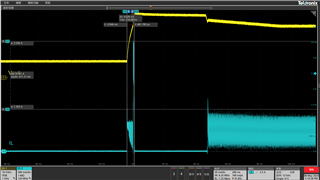
Test the LP8867C with the input RUSH waveform as shown in the attachment, the yellow wire is the supply output voltage and the blue wire is the inductive current near the SW side. There were two rushes, the first time the VIN was powered up and the second time the EN was pulled and the boost started.
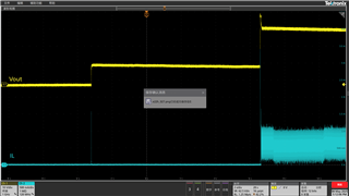
The peak value reached 3.6V. It lasts several hundred μs.

Q1: The chip's SW current limit for the first trigger current limit, mechanism is > 3.35A for 1.6s, then relax the limit to 3.7s for 1.6s, then switch off the FET. If limit is not triggered the first time, > 3.35A turns the internal FET directly off during the next cycle. Do I understand it correctly?

Q2: Does the chip not detect power-up rush, only after EN is pulled?

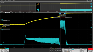
Q3: See the accessory waveform, is there a risk of triggering limit current?

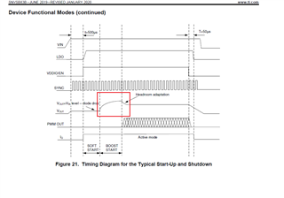
Q4: Please consult, after pulling the EN, Vout starts to increase pressure, but there is a time difference of 15ms to SW, What is the state of the IC at this time?

  • Hi Alan,

    Q1: The chip's SW current limit for the first trigger current limit, mechanism is > 3.35A for 1.6s, then relax the limit to 3.7s for 1.6s, then switch off the FET. If limit is not triggered the first time, > 3.35A turns the internal FET directly off during the next cycle. Do I understand it correctly?

    The SW limit will be 3.7A first and then changed to 3.35A after 1.6s. Then toggles between 3.35A and 3.7A in a 1.6s intervals.

    Q2: Does the chip not detect power-up rush, only after EN is pulled?

    The power-up inrush is caused by the charging process of output capacitance. The current goes though inductor, diode, and then into the output capacitor. It means this current cannot be controller by LP8876C-Q1.

    Q3: See the accessory waveform, is there a risk of triggering limit current?

    Seems that the current limit has already reached during the start-up (the current limit range is wide, 3.3~4.1A). Generally, it's acceptable to reach the limit during the start-up process.

    Q4: Please consult, after pulling the EN, Vout starts to increase pressure, but there is a time difference of 15ms to SW, What is the state of the IC at this time?

    Could you please tell me where's the 15ms?

    Best regards,

    Suchen

  • Hi Suchen,

    Thanks for your help!

    Could you please tell me where's the 15ms?

    This is where the SW starts the switch action before the boost, how is the chip done, what is the state of the chip?

  • Hi Alan,

    If you're talking about the BOOST START period in Figure 21, the boost converter is already running, and you can see active Vsw and inductor current waveforms. But the PWM dimming doesn’t start until after the BOOST START phase, and only then current will be sink from the OUTx pins.

    As for the non-switching period in the waveform you showed, it's a common waveform because the initial voltage is higher than the final optimized voltage, the target boost voltage will be adjusted to a lower value. Hence the inductor current is regulated to 0 in that progress.

    Best regards,

    Suchen

  • Hi Suchen,

    Thank you for your answer! For the Rush current of the appliance on the customer two further questions are as follows:

    1. Is this RUSH after EN pulled directly proportional to the loop regulation speed? The specification book does not contain an overhead wave for the input current.

    2.Customers are worried that rush will get bigger at high and low temperatures, triggering current limit. If you want to reduce rush, help with suggestions on what to do.

    In addition: Append a question, you said the current limit was 3.7A first, lasting 1.6s, which time interval does this 1.6s refer to? Is the current limit 3.7 or 3.35 for this RUSH duration of the EN pull-out?

  • Hi Alan,

    1. Is this RUSH after EN pulled directly proportional to the loop regulation speed? The specification book does not contain an overhead wave for the input current.

    It's related to the loop speed. There's no inductor current waveform in the datasheet. There's only LED current waveform in the OUTx pin.

    2.Customers are worried that rush will get bigger at high and low temperatures, triggering current limit. If you want to reduce rush, help with suggestions on what to do.

    Cycle-by-cycle current limit is a simple mechanism and exists in any condition (like high/low temperature). It could be triggered during startup or load transient. Does the customer mean it's not acceptable to trigger a current limit? 

    In addition: Append a question, you said the current limit was 3.7A first, lasting 1.6s, which time interval does this 1.6s refer to? Is the current limit 3.7 or 3.35 for this RUSH duration of the EN pull-out?

    This interval is a long period, hence it's not showed in the timing waveform. The limit is 3.7A in the beginning.

    Best regards,

    Suchen

  • Hi Suchen,

    Does the customer mean it's not acceptable to trigger a current limit? 

    The customer mainly has some concerns and wants to minimize this possible risk.

    Q1: 8867 No comp, customer can't adjust response rate, how is the rush of our EVM?

    Q2: The attached circuit diagram, please help assess whether the circuit speed design problem of the IC itself or the peripheral circuit design problem.

    Q3: Is there any suggestion to reduce the peak value of rush?

    8867.pdf

  • Hi Alan,

    Q1: 8867 No comp, customer can't adjust response rate, how is the rush of our EVM?

    We have a similar inductor waveform during startup. The current reaches the current limit. And it's true that we don't have much flexibility on the loop because the comp circuit is built in chip. 

    Q2: The attached circuit diagram, please help assess whether the circuit speed design problem of the IC itself or the peripheral circuit design problem.

    I saw there's a power line FET but LP8867C-Q1 version is used. Does the power line FET are currently not used and bypassed?

    Q3: Is there any suggestion to reduce the peak value of rush?

    In general, the current limit is only reached once during the start-up, so it does not significantly affect thermal performance or efficiency. As long as the inductor does not saturate and the diode current is not exceeded, there should be no serious concern.

    Best regards,

    Suchen