This thread has been locked.

If you have a related question, please click the "Ask a related question" button in the top right corner. The newly created question will be automatically linked to this question.

BQ25798: VSYS load current impacts charge termination current

Part Number: BQ25798
Other Parts Discussed in Thread: BQ40Z50

Tool/software:

Hi there—we are evaluating whether it is worthwhile to increase VBUS from 9 V to 12 V in an effort to increase available input power at the expense of BQ25798 efficiency. The results of a complete charging cycle are as follows:

The plot is obtained by continuously polling the BQ25798 and our gas gauge (BQ40Z50) over I2C. Input current and charger temperature are read from the BQ25798, while the remaining parameters are read from the gas gauge. We can see that charger temperature has reached the thermal regulation limit (120 deg. C) pretty easily, so battery current is throttled back from the programmed charging current (5.0 A); this seems expected.

However, the logs recovered from this test indicate that charging was not terminated until battery current (as read from the gas gauge) reached 250 mA; this is much lower than the programmed termination current of the BQ25798 (480 mA). As a result, charge time was roughly 2 hours longer than expected.

When I arrived at my bench a short time later, I removed and re-inserted the USB-C charger and found that charging immediately re-started. I dumped the BQ25798 registers; the results are as follows:

     0  1  2  3  4  5  6  7  8  9  a  b  c  d  e  f
00: 02 01 b8 01 f4 6a 01 2c 8c 0c 03 00 dc 4b 3d a2
10: 80 00 10 01 14 aa c0 7a 55 01 2c 0f 90 01 00 00
20: 00 00 df 94 00 00 00 00 ff c7 7f 1f ff fc 80 00
30: 00 01 37 01 04 2f 13 2e f4 2e f6 11 37 11 4b 02
40: 54 00 35 00 0d 00 2a 00 19 ff ff ff ff ff ff ff

From this, we can conclude that:

  • IBAT = 260 mA < ITERM = 480 mA
  • VBAT = 4407 mV > VREG - VRECHG = 4200 mV
  • CHG_STAT = 4 (CV mode)

All three conditions defined in section 9.3.9.3 of the datasheet with regard to charge termination are satisfied—why does charging continue?

On a hunch, I disabled a few hundred mA worth of illumination downstream of VSYS; charging immediately terminated. I then re-enabled the load, and charging did not resume. With the load still enabled, I removed and re-inserted the USB-C charger to create the original failure condition in a more controlled setting. Charging immediately resumed again, and the BQ25798 registers report a similar scenario:

     0  1  2  3  4  5  6  7  8  9  a  b  c  d  e  f
00: 02 01 b8 01 f4 2b 00 c8 8c 0c 03 00 dc 4b 3d a2
10: 80 00 10 01 14 aa c0 7a 55 00 c8 0f 90 01 00 00
20: 00 00 00 00 00 00 00 00 ff c7 7f 1f ff fc 80 00
30: 00 03 7e 01 79 13 21 13 09 13 13 11 39 11 50 02
40: 54 00 2e 00 00 00 00 00 19 ff ff ff ff ff ff ff

Like before, we see:

  • IBUS = 894 mA
  • IBAT = 377 mA < ITERM = 480 mA
  • VBAT = 4409 mV > VREG - VRECHG = 4200 mV
  • CHG_STAT = 4 (CV mode)

After the load is disabled, the BQ25798 registers are found to be as follows:

     0  1  2  3  4  5  6  7  8  9  a  b  c  d  e  f
00: 02 01 b8 01 f4 2b 00 c8 8c 0c 03 00 dc 4b 3d a2
10: 80 00 10 01 14 aa c0 7a 55 00 c8 0f f0 01 00 00
20: 00 00 00 80 00 00 00 00 ff c7 7f 1f ff fc 80 00
30: 00 00 e4 00 00 13 a7 13 98 13 96 11 25 12 15 02
40: 54 00 35 00 00 00 00 00 19 ff ff ff ff ff ff ff

Now, we see:

  • IBUS = 228 mA
  • IBAT = 0
  • VBAT = 4389
  • CHG_STAT = 7 (done)

The results seem to suggest that current drawn from VSYS may impact the current used to judge termination, as opposed to IBAT alone—are these results expected? If so, is there any way to work around this behavior? Thank you in advance for your support—in case I can provide any additional information, please let me know.

  • Hi Jeff,

    I haven't seen this before. Any chance you can probe a current probe on IBUS?  There is an known issue where the charger bounces between DCM and CCM around this input current range when PFM is off.  If you don't have a current probe, we can look at SW1 because in DCM the low side FET doesn't turn and the charger rides the body diode.  Also, you can try turning on PFM and see that that helps.

    Regards,

    Jeff

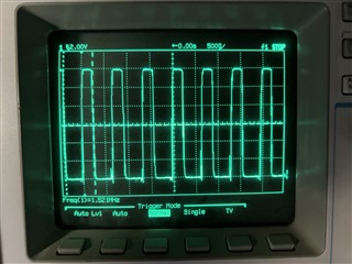
  • Hi Jeff—thank you for the rapid feedback. I can't get hold of a current probe quickly, but I measured the following waveform at SW1:

    It holds steady at 1.5 MHz, and doesn't seem to be entering DCM. SW2 holds steady at VREG. The BQ25798 registers at the time of the measurement appear as follows, with IBAT = 444 mA < ITERM = 480 mA:

         0  1  2  3  4  5  6  7  8  9  a  b  c  d  e  f
    00: 02 01 b8 01 f4 24 01 2c 8c 0c 03 00 dc 4b 3d a2
    10: 80 00 10 01 14 aa c0 7a 55 01 2c 0f 90 01 00 00
    20: 00 00 00 80 00 00 00 00 ff c7 7f 1f ff fc 80 00
    30: 00 01 84 01 bc 2e fc 2e f6 2e e9 11 37 11 4f 02
    40: 52 00 38 00 13 00 30 00 19 ff ff ff ff ff ff ff

    I did try re-enabling PFM mode for grins, but there was no change—I think this load current is too high. PFM mode is not an option for us anyway; it has been disabled for the reason described in this thread.

    I've since reproduced this issue on every sample I've tried (4 so far)—as far as I can tell, the issue corresponds to the load current on VSYS. We're in the process of evaluating a new revision to our design, which adds some additional load on VSYS—it may explain why we haven't seen this issue before.

    This issue is a blocker for us—is there anything else we can check? We can potentially disable or reduce the load during charging, but I imagine the load current for which this phenomenon is guaranteed not to happen may be difficult to predict.

    In the absolute worst case, we can set EN_TERM = 0 and make the BQ40Z50 the arbiter of charge termination—however, this would involve a change to the gas gauge's flash, and it's an inopportune time to do so.

    On a related note—can you share more details about the CCM/DCM issue with PFM mode disabled? Is there anything we should be aware of, or possibly work around?

    Thanks again for your continued support—in case I can provide any additional information, please let me know.
  • Hi Jeff,

    I am bit puzzled as I haven't had any complaints about termination current set this high.  I have had complaints with termination current set down below 120mA.  I will schedule some bench time to look at this.  Can you remind me if you placed the 0.1uF SYS to GND capacitor as recommended in the datasheet?  The current sense amp that measures charge current is very noise sensitive.  To that end, I am curious what the charger's ADC reports for charge current?  Is it accurate?  The ADC uses the same current sense amp as the ICHG loop and termination comparator.  Another option might be to lower the charge current register setting below 1A once the current has tapered below 1A.  ICHG set < 1A makes the battery FET more resistive and therefore gives a more accurate current measurement.  This has worked for others who wanted ITERM <120mA. 

    I do not recommend disabling termination and using the BQ40Z50 charge FET to terminate.  When EN_TERM=0, BAT OVP threshold drops from 105%*VREG to VREG itself.  This can result in oscillating in and out of charge, term, OVP, recharge.  You could use the BQ40Z50 current measurement to look for termination and then have the software disable charge.  But that might require changing the 40Z firmware.

    The CCM/DCM is essentially a due to there being no hystersis getting in/out of each.  So there is a narrow input current range (175-250mA) where the charger essentially has a modal (as opposed to small signal) oscillation in/out of CCM and DCM.  Your power level is higher than that and waveform proves it.

    Regards,

    Jeff

  • Hi Jeff—thank you for the update! Owing to your gracious help, I think we've solved this one (more on that in a bit). But first, in response to your feedback:

    Can you remind me if you placed the 0.1uF SYS to GND capacitor as recommended in the datasheet?

    I can confirm this capacitor is present, and highlighted below:

    We cannot place any components on the bottom side due to mechanical constraints, hence this capacitor being on top and near the DUT.

    To that end, I am curious what the charger's ADC reports for charge current?  Is it accurate?

    The ICHG reported by the BQ25798 (registers 0x33–0x34) and the BQ40Z50 (SBS command 0x0A) always seem to agree with one another within 5%, with the BQ40Z50 known to be a bit high as these packs are not calibrated on a per-sample basis yet.

    Another option might be to lower the charge current register setting below 1A once the current has tapered below 1A.

    I lowered the charge current to 800 mA (registers 0x03–0x04 = 0x0050), but the behavior remained the same; CHG_STAT remained 3'b100 (CV mode) while charging current continued to fall toward 400 mA. I removed and re-inserted the USB-C charger in case restarting the charging cycle might make a difference, but the behavior reproduced immediately.

    We have a couple different means to control illumination here—the first is a very crude PWM method in which the entire LED strings are rapidly turned on and off, resulting in a lot of trash placed on VSYS. The second is a constant-current LED driver, the latter of which hadn't been exercised yet as the FW isn't fully ready.

    Still suspecting that this issue is indeed noise related, I switched the control source to the constant-current LED driver, and the problem is solved—ICHG falls from 0x1df (479 mA) to 0x1d5 (469 mA), and then to zero. This was with the charging current limit restored to 5 A—interestingly enough, the termination threshold was a bit farther off (428 mA) with the charging current limit lowered to 800 mA.

    It seems we are out of the woods now—to close out a few other topics for posterity:

    I do not recommend disabling termination and using the BQ40Z50 charge FET to terminate.

    I am aligned with you; this would have been relatively painful to implement at this stage anyway.

    You could use the BQ40Z50 current measurement to look for termination and then have the software disable charge.  But that might require changing the 40Z firmware.

    This would have been a viable workaround, and would not have required any changes to the BQ40Z50 flash in our particular case.

    The CCM/DCM is essentially a due to there being no hystersis getting in/out of each.  So there is a narrow input current range (175-250mA) where the charger essentially has a modal (as opposed to small signal) oscillation in/out of CCM and DCM.

    It seems that our input current may fall into the high end of this range during some idle conditions—even though we didn't see it here, maybe it would occur across P/V/T. What kind of system-level behavior would we see if this issue were to occur?

  • Hi Jeff,

    Great news!  You might be able to tune out the SYS noise with a different size decoupling cap.  Odd that lowering the ICHG setting made things worse.

    The modal oscillation in usually in the audible range so the ceramic caps start singing.

    Regards,

    Jeff

  • Thanks again Jeff—I'm aligned with you on all of this. I'll reach out in case I have any additional questions. Have a great week!