Other Parts Discussed in Thread: LM3435,
Tool/software:
Hi TI E2E
Before, I used the LM3435 as our Head Mount Display LED driver.
and the result is great, but in some rare case, such as the LED control is failed (I2C write the led current control failed)
the LM3435 will work in a very high current output, it will let our battery and HMD PCB broken,
so, I want to try LM3549 in our new Head Mount Display.
This is my Software and Hardware Setting, I'm not sure is correct or not.
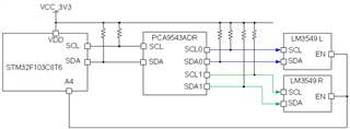
LM3549 I2C device address could not be selected, so I choose the I2C MUX PCA9543.
The hardware connection path is STM32F1(MCU)_I2C2->PCA9543(I2C MUX)->LM3549_Right and LM3549_Left(LED Driver)->LCOS
in the PDF TI_LM3549 pdf, as shown below, This is a part of the LED driver design(hardware is refer from the LM3549 EVK).
1.I pull down the the A0 and A1pin from PCA9543(PCA9543.schDoc,part number U10), cause the I2C devices is only two.
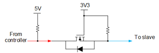
2.As the same page, I use four MOS to prevent the current leakage from I2C slave device to master.(I'm not sure this method is correct or not)
3.In the software control as show below
(3-1)MCU and PCA9543 turned on as the same time
(3-2)pull high the I2C reference voltage for LM3549
(3-3)pull high the LM3549 enable
(3-4)set the PCA9543 for the SD0 and SC0
(3-5)configure the LM3549_Right
(3-6)set the PCA9543 for the SD1 and SC1
(3-7)configure the LM3549_Left
(3-8)Turn off the the PCA9543 to prevent some malfunction
/*enable the lm3549 power source and the lm3549 i2c reference voltage start*/
/*add the PCA9543 control for the two lm3549 which the i2c device address is same*/
uint8_t pca9543_cmd_R = 0x01;
uint8_t pca9543_cmd_L = 0x02;
uint8_t pca9543_cmd_off = 0x00;
HAL_GPIO_WritePin(GPIOB,V3V3_EN_Pin_Pin,GPIO_PIN_SET);//enable the i2c refernece voltage for lm3549
HAL_GPIO_WritePin(GPIOA,LM3435_EN_Pin,GPIO_PIN_SET);//pull high the lm3549 reset pin, let it on work.
//config the right lm3435
HAL_I2C_Master_Transmit(&hi2c2, 0x70 << 1, &pca9543_cmd_R, 1, 10);
set_bank0(&hi2c2);
Set_RGB_Current(&hi2c2,153,153,153);//15% duty = 1023*0.15 ->nearby 153
//config the left lm3435
HAL_I2C_Master_Transmit(&hi2c2, 0x70 << 1, &pca9543_cmd_L, 1, 10);
set_bank0(&hi2c2);
Set_RGB_Current(&hi2c2,153,153,153);//15% duty = 1023*0.15 ->nearby 153
//turn off the pca9543 channel
HAL_I2C_Master_Transmit(&hi2c2, 0x70<<1,&pca9543_cmd_off,1,10);
Thank you
Best Regard Steve