Tool/software:
Hi team,
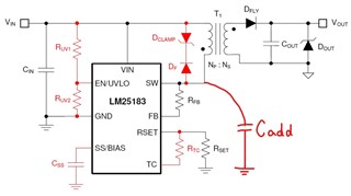
I consider adding a ceramic capacitor between the SW pin and GND, as shown in the figure below.
Are there any trade-offs with adding a ceramic capacitor?

Best regards.
This thread has been locked.
If you have a related question, please click the "Ask a related question" button in the top right corner. The newly created question will be automatically linked to this question.
Tool/software:
Hi team,
I consider adding a ceramic capacitor between the SW pin and GND, as shown in the figure below.
Are there any trade-offs with adding a ceramic capacitor?

Best regards.
LM25183-Q1 flyback operates in Discontinuous Mode or Boundary Conduction Mode depending on the load. The waveform below describes how the device captures isolated output information based on the measured voltage at the SW pin. Notice, when the secondary current reaches zero, a resonant ring is observed on the SW node due to the Magnetizing inductance and the SW node capacitance. Therefore, adding an external capacitor on SW is not recommended because the SW waveform will produce a VFB error that may not accurately reflect the real condition of the load current.

Steve
Dear Steve,
Thanks for your reply.
The purpose of adding a ceramic capacitor to the SW terminal is to reduce noise.
As another method of noise reduction, I consider adding a CR snubber between Vin and SW.
Is this a correct idea?
Also,if I add a CR snubber, is there anything I should be careful of?
Please let me know.
Best regards,
Refer to previous answer. The high frequency ringing on the rising edge of SW should be clamped as shown in the waveform I shared. The low frequency ring is only appearing when operating in DCM and this is not going to be altered by adding C or RC from SW to GND.
Steve