Tool/software:
Hello,
I'm using the TPS25751 USB Type-C and USB PD Controller(https://www.ti.com/lit/ds/symlink/tps25751.pdf), and I would like to reconfigure pin 17 (I2Cc_IRQ) to function as GPIO12, as noted in the datasheet. While the datasheet mentions that this pin can be reconfigured, it does not provide the steps required to perform this change.
Could you please clarify the following:
- If I’m using the i.MX8M Plus SoC as the host, how should I implement this pin reconfiguration from the SoC side?
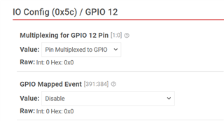
- Is this reconfiguration done using the TI Application Customization Tool?
- What specific settings in the tool or registers need to be modified to disable the I²C controller and enable GPIO12?
- Must this configuration be loaded at boot via an external EEPROM, or can it be applied as a patch from the host over I²C?
Any guidance, documentation, or example configurations would be greatly appreciated.