This thread has been locked.

If you have a related question, please click the "Ask a related question" button in the top right corner. The newly created question will be automatically linked to this question.

TPSM82823A: Frequency response in the specific conditions

Part Number: TPSM82823A


Tool/software:

Hi team,

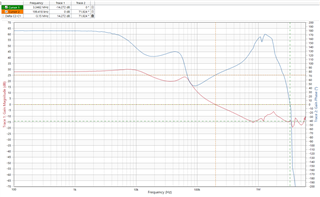
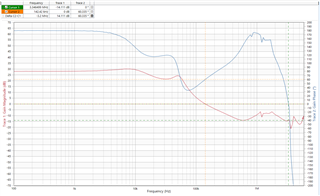
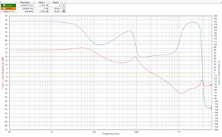
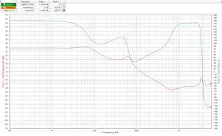
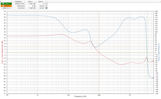
Could you please kindly let simulate the frequency response(Gain - Frequency, Phase - Frequency) of the input and outpu conditions below?

Input voltage: 3.3V

Output voltage: 1.5V

Output current: 1A

Output capacitor: GRM155R60J226ME11 x 2pcs(Need to consider DC bias which is -36.3%)

No Cff

Best regards,

Shunsuke Yamamoto

  • Hello Shunsuke,

    thanks for reaching out in E2E.

    There is no AC simulation model available for the TPSM82823A. The available PSPICE model is for transient simulations only.

    Best regards,

    Andreas.

  • Hi Andreas,

    Could you please kindly take measurement for my customer?

    Best regards,

    Shunsuke Yamamoto

  • Hello Shunsuke,

    I don't have GRM155R60J226ME11 capacitors available. Ordering them would take ca. one week. Is it OK for the customer to wait so long?

    Best regards,

    Andreas.

  • Hi Andreas-san,

    Thank you for the reply. He mentioned he doesn't need to take the measurements. Sorry for asking. By the way, do we have plans to release AC simulation model of TPSM82823A?

    Best regards,

    Shunsuke Yamamoto

  • Hi Andreas-san,

    After all, he would like to have the measurements results of the frequency response, and he is okay to wait for over one week. Sorry for changing a lot, and could you please kindly take measurements? He changed the input and output conditions below.

    1. 

    Input voltage: 3.3V

    Output voltage: 1.5V

    Output current: 1A

    Output capacitor: GRM155R60J226ME11 x 3pcs(Need to consider DC bias which is -36.3%)

    2.

    Input voltage: 3.3V

    Output voltage: 0.7V

    Output current: 1.9A

    Output capacitor: GRM155R60J226ME11 x 3pcs(Need to consider DC bias which is -11%)

    Best regards,

    Shunsuke Yamamoto

  • Hello Shunsuke,

    thanks for the update.

    There are no plans at the moment to create a AC simulation model for the TPSM82823A.

    It turned out to be difficult to order these capacitors, so I switched to a plan B: I used an available capacitor type and varied the number of caps to analyze the trend for stability. From the datasheet recommendation it is expected that the risk for instability arises with too high output cap values. So I selected GRT188R61A226ME13, which has less DC bias (-23.8% at 1.5V and -4.9% at 0.7V) and which would be more critical for possible instability in the TPSM82823A application when too many caps are used. This would give us some margin for translating the conclusion to the desired GRM155R60J226ME11 capacitor.

    Here are the results of the analysis:

    Vin = 3.3 V, Vout = 0.7 V, no CFF:

    Cout Crossover Frequency Phase Margin Gain Margin
    1 x 22 μF 395.9 kHz 82.5 ° 14.3 dB
    2 x 22 μF 199.4 kHz 71.9 ° 14.3 dB
    3 x 22 μF 142.4 kHz 60.3 ° 14.1 dB

    Vin = 3.3 V, Vout = 1.5 V, no CFF:

    Cout Crossover Frequency Phase Margin Gain Margin
    1 x 22 μF 228.5 kHz 59.4 ° 11.3 dB
    2 x 22 μF 126.5 kHz 44 ° 11.5 dB
    3 x 22 μF 99.7 kHz 33.3 ° 11.5 dB

    The datasheet is recommending a Cout range from 10 μF to 47 μF. The measured results for Vout = 1.5 V are confirming this recommendation. So, a Cout of 3 x 22 μF is causing a quite concerning low phase margin. It would be better to use a lower Cout value (for example 2 x 22 μF).

    For Vout of 0.7 V the impact of higher Cout values seems to be not so critical. 3 x 22 μF is still showing a good phase margin.

    For the desired capacitor GRM155R60J226ME11, which has a higher DC bias, we can conclude now, that for Vout = 0.7 V it should be OK to use Cout of 3 x 22 μF. For Vout = 1.5 V it would be recommended to follow the datasheet and use only 2 x 22 μF.

    Let me know if you have any questions.

    Best regards.

    Andreas.

  • Hi Andreas-san,

    I will confirm if my customer is acceptable for your plan. By the way, you can place an free sample order via MURATA's web site.

    https://www.murata.com/en-us/products/productdetail?partno=GRM155R60J226ME11%23 

    Best regards,

    Shunsuke Yamamoto

  • Hi Andreas san,

    Thank you so much for the continuous support. I apologize for asking questions a lot. Could you please kindly create the comparison of GRM155R60J226ME11 and GRT188R61A226ME13?

    Do you mean the analysis is the calculated result, right? If it is possible, could you please take measurement of ot to proove your calculation is correct?

    Best regards,

    Shunsuke Yamamoto

  • Hi Shunsuke,

    thanks for pointing me to the free samples option. I was not aware.

    My results were measured with capacitor GRT188R61A226ME13 installed at the EVM and not calculated results.

    The most relevant parameter is the effective capacitance after DC bias derating.

    For GRT188R61A226ME13 the DC bias derating is -23.8% at 1.5V and -4.9% at 0.7V. For GRM155R60J226ME11 the DC bias derating is -36.3% at 1.5V and -11% at 0.7V. So the GRT188R61A226ME13 has a higher effective capacitance for both conditions. A higher effective capacitance is more critical for stability. But at 0.7V the measured phase margin was OK even at the higher effective capacitance. Thus I was concluding that the phase margin will be also OK with the lower effective capacitance of the GRM155R60J226ME11. At 1.5V the measured phase margin was too low for 3x22uF and marginal for 2x22uF. So I concluded the 2x22uF should be OK for the lower effective capacitance of GRM155R60J226ME11.

    So then I will have to repeat the measurements with the free samples of GRM155R60J226ME11. I will give an update once the samples are available.

    Best regards,

    Andreas.

  • Hi Andreas-san,

    Thank you for the support! We are looking forward to the results of phase margin and gain margin with GRM155R60J226ME11. I got additional request from my customer. My customer would like to add Cff to TPSM82823A on the case of Vin = 3.3V, Vout = 1.5V and 3 x 22uF(GRT188R61A226ME13). Is it possible for you to estimate the Cff value to meet the phase margin of over 45 degree?

    Best regards,

    Shunsuke Yamamoto

  • Hi Andreas-san,

    May I know if you could share the measured curve of the loop resonses? Total 6 curves are needed since my customer has requested. Sorry for asking a lot.

    Vin = 3.3 V, Vout = 0.7 V, no CFF:

    Cout Crossover Frequency Phase Margin Gain Margin
    1 x 22 μF 395.9 kHz 82.5 ° 14.3 dB
    2 x 22 μF 199.4 kHz 71.9 ° 14.3 dB
    3 x 22 μF 142.4 kHz 60.3 ° 14.1 dB

    Vin = 3.3 V, Vout = 1.5 V, no CFF:

    Cout Crossover Frequency Phase Margin Gain Margin
    1 x 22 μF 228.5 kHz 59.4 ° 11.3 dB
    2 x 22 μF 126.5 kHz 44 ° 11.5 dB
    3 x 22 μF 99.7 kHz 33.3 ° 11.5 dB

    Regarding the addition of Cff, my customer requested to add Cff of 5.6pF and 12 pF at first. If these values cannot still satisfy increase the phase margin requirement, please choose the appropriate value.

    Best regards,

    Shunsuke Yamamoto

  • Hello Shunsuke,

    sorry for the late reply, but I was not in the office last week.

    The capacitor samples have not arrived yet. It seems the shipment is stuck.

    Every variation in CFF is doubling the effort for board modification and measurements.

    Maybe it would be more efficient if you would help to provide one or more TPSM82823AEVM to the customer, so that all customer specific BOM variations can be evaluated by the customer itself. What do you think?

    Best regards,

    Andreas.

  • Hi Anreas-san,

    Thank you for the reply. I understand your suggestion. I will let my customer select the appropriate Cff by using the EVM, so please follow up the request below. I will try to close other requests from my customer.

    "

    May I know if you could share the measured curve of the loop resonses? Total 6 curves are needed since my customer has requested. Sorry for asking a lot.

    "

    Best regards,

    Shunsuke Yamamoto

  • Hi Shunsuke,

    do you mean the curves for the capacitors GRT188R61A226ME13, that I summarized in the table fro no CFF?

    Here are these curves:

    Vin = 3.3 V, Vout = 0.7 V, no CFF, Cout = 1 x 22 μF:

    Vin = 3.3 V, Vout = 0.7 V, no CFF, Cout = 2 x 22 μF:

    Vin = 3.3 V, Vout = 0.7 V, no CFF, Cout = 3 x 22 μF:

    Vin = 3.3 V, Vout = 1.5 V, no CFF, Cout = 1 x 22 μF:

    Vin = 3.3 V, Vout = 1.5 V, no CFF, Cout = 2 x 22 μF:

    Vin = 3.3 V, Vout = 1.5 V, no CFF, Cout = 3 x 22 μF:

    Best regards,

    Andreas.