This thread has been locked.

If you have a related question, please click the "Ask a related question" button in the top right corner. The newly created question will be automatically linked to this question.

UCC5350: [Switching Characteristics]TIMING FOR Output-signal rise time and Propagation delay

Part Number: UCC5350

Tool/software:

Hi team,

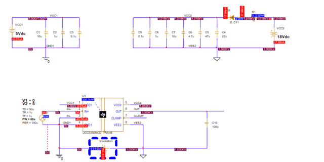
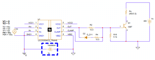
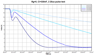
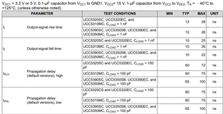
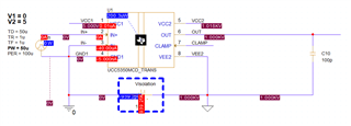
 we want to evaluate the UCC5350MCDR device timing, after using the UCC5350MCD_TRANS-PSpiceFiles file to reproduce the performance on datasheet like tR 10ns ,tPLH = 65ns~100ns at 100pf load. if it works, we will add custom circuit for real result. but the PSpice simulation result seems different , can you help to check how we can get the target result here?

what we set now :

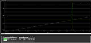
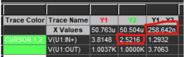
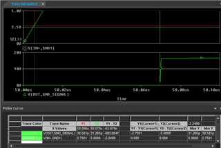
result:  output as 260ns for tPLH 

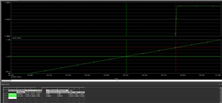
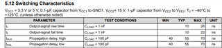
tR as 9.25ns is correct.

  • Hi Allen, 

    Can you share your PSPICE simulation files? I will investigate further. The tp_LH propagation delay of UCC5350 is 55ns, and the tp_HL is about 54ns. The wide 100ns max tolerance is based on process corners and temperatures. 

    This is a very slow input rise time. Our propagation delay does not start until the input exceeds the input threshold. In this case, the propagation delay should be measured starting from when the IN+ is 0.55 x 5V, or 2.75V. Is 260ns measured from this threshold?

    Best regards,

    Sean

  • Hi Sean,

     i am using the sllm368a.zip file download by TI.com. 

    sllm368a.zip

     and i just delete the output circuit as below and target to get the tp_LH propagation delay as datasheet mentioned.

    and yes, i measure the 0.5 * Vin + to 10% * Vout, so we can see the concur details here:

  • Hi Allen,

    This is strange. I am not the author of this model unfortunately. However, I found that the t_PLH goes back to 60ns if you use a 10ns tr and tf:

    It should be 55ns typical, but at least this result is within the tolerance UC5350-Q1 datasheet tolerance:

    Hopefully this result can convince them to test the device with an EVM.

    Best regards,

    Sean

  • Hi Sean,

     tks for the checking here,

     the T_PLH is correct now, the tR becomes 700ps level which far away from the spec as 12ns typ. seems still have a bug here. appreciate for further checking. 

  • Hi Allen, 

    Not all of the datasheet metrics were modeled in detail. The primary objective was to create a useful simulation tool.

    Best regards,

    Sean

  • Hi Sean,

     if the simulation file is not fully correct for the datasheet,  so customer some test may not work here.

     in another words, could you help to provide the curve of tplh vs  Load Capacitance?

    (Why: the datasheet show CLOAD = 1 nF /100pf, but customer system may have different setting as below, so customer want to know the curve of real tplh parameters.)

    below is the customer SCH:

  • Hi Allen,

    Here is a measurement I have for all of the UC53X0 devices driving a large 330nF load. As you can see, the tpLH is still a nominal 55ns for all these devices.

    The rise time is loaded by the 330nF, so depending on how you calculate tpLH, you may need to account for the peak output current and the load. However, the start of the rise time is still delayed by the same 55ns, regardless of the loading condition. The same is true for tpHL, which is 54-55ns. 

    Best regards,

    Sean

  • Hi Sean, 

     tks for the data, it is not that so clear to understand full of the curve.

     it seems the Vout as 18V here, and due to the large load as 330nf, so i will cause the pulse at beginning?

     but i can not see the input timeline to compare a tplh,  appreciate help to define why  the tpLH is still a nominal 55ns here!

    but base on your test ,i think the tplh is still follow the datasheet with CLOAD = 100 pF ~330nF?

  • Hi Allen, 

    The pulse at the beginning is due to series inductance. It presents a transient high impedance to the gate driver's output.

    I have set 50ns/division in the first tpLH graph. My oscilloscope for this measurement was triggered on the input at 2.5V, as the input was a 5V square wave.

    You can see that the output starts to rise at around 50ns.However, it reaches the 9V mid-point to the 18V supply at different times, depending on the gate driver's drive strength.

    In conclusion, while Cload can affect the gate driver's rise time, it does not delay the time it takes fot the output to start rising after receiving an input signal.

    Best regards,

    Sean