Tool/software:
Hi TI team,
We are currently evaluating a product concept with the TPS25751, where the customer wants to design an external expansion dock that can also provide power to the host system. Therefore, USB PD Role Swap support is required. The intended behavior is as follows:
-
Initially, the host is in a Dead Battery state (no internal battery), so the dock provides power after negotiating via the CC pins.
-
The dock only supports USB 2.0 data as a UFP.
-
After the host becomes power ready, it initiates a Data Role Swap to switch the dock into UFP mode for data communication.
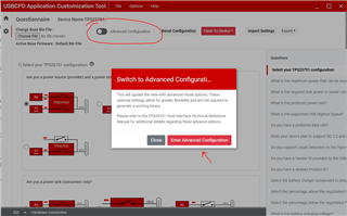
We noticed that the TPS25751 supports a Web-based GUI and pre-configured firmware:
https://www.ti.com/product/TPS25751
We have the following questions:
-
Can the TPS25751 fulfill our product requirements? What considerations or limitations should we be aware of?
-
Is it feasible to achieve this design without an MCU on the dock side, using only the Web-based GUI and pre-configured firmware?
-
The TPS25751 datasheet mentions that "The GPIO is driven high when the data role of any port in the PD controller is UFP."
Since our dock only supports UFP, we plan to use a USB MUX to disconnect the USB data lines initially, and then connect them after confirming the role has swapped to UFP using the GPIO signal from TPS25751.
Is this approach viable? -
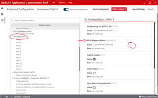
How can we configure the GPIO event "The GPIO is driven high when the data role of any port in the PD controller is UFP"?
We didn’t find this option in the Web-based GUI. Is it possible to implement this function through the pre-configured firmware in a no-MCU design?
Thanks for your support!