This thread has been locked.

If you have a related question, please click the "Ask a related question" button in the top right corner. The newly created question will be automatically linked to this question.

UCC28951-Q1: Problem with not being able to exit Burst Mode

Part Number: UCC28951-Q1
Other Parts Discussed in Thread: UCC28951

Tool/software:

V_in =390V

V_out = 28V 

P_out =700W 

N = 12

Hello,

I am working with a DC/DC converter with the above values. My R_tmin resistor has a value of 12k. I have no problems with output regulation. I have loaded up to 1, 5 and maximum 14 A. However, I cannot get out of burst mode at all load values. For this reason, there is an audible noise in the 10 kHz band from the pickups. I did not do the load tests I mentioned for more than 10 seconds. If I continue, something will be damaged. How can I get out of burst mode? Where is the error?

Best regards.

  • Have you used the calculator online to design your system? Please double check your system design against the calculator.

  • Hi Ning,

    When I designed circuit, I used calculator  but calculator has a transformer duty cyle rule which has %66. I changed this rule %90 because UCC28951 gives %92 duty cycle. Other calculations was did by using calculator sheet.

  • have you tried to change it back to 66% and see any other parameters change? 

    Dmax is locked in the calculator. I am not sure how you can change it.

  • we don't change anything on design sheet. We changed only duty cycle max parameter (%66 to %90). We must use 12 turn ratio because we want to use syncronus rectifier on output side,  therefore we must have low voltage on outputside. Is duty cycle cmax value related to burst mode ? If we have %86 duty cycle on primary side, we have to go out from burst mode because we have 12k Rt_min value. In that situation, t_min value should be approx. 100 nS. %86 duty cycle on primary side means that we have approx. 2.4 uS t_on time value. In that situation, we can go out from burst mode but it's not.

  • Hi Cihangir,

    I need few more details to understand the problem better.

    Can you please measure and let me know what is the duty when the converter is operating in the burst mode? Is it higher than Tmin?

    Regards,
    Deepak K

  • Hi Cihangir,

    Based on the details you have provided, I can think of one possibility. The issue can be due to higher output capacitance. The high output capacitance can be holding the output voltage in the regulated condition for long which is causing the duty to be less than Tmin and causing the burst mode enable scenario. This can be due to either converter output bulk capacitance or the load input bulk capacitance, if you are using an electronic load. So, I suggest you to do following test.

    1. Try reducing converter output bulk capacitance to 3/4th of the current value (I won't suggest you reducing the output capacitance drastically since it can cause stability issues in the converter). If this makes any difference in the converter performance, you can try reducing the output capacitance further and see whether it is helping more.
    2. If above test is a success, you have to verify whether this is causing due to converter output bulk capacitor or electronic load input capacitance. To verify this, you can use a resistive load instead of electronic load and try running the converter with its actual output bulk capacitance. If the converter is coming out of burst mode, that means the issue is due to the input capacitance of electronic load and if the converter is not coming out of burst mode try doing the first test again with resistive load.

    Please update me with the results of above tests so that I can help you further.

    Regards,
    Deepak K

  • Hi Deepak,

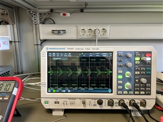
    Thank you for your answer. I will try this. Can it be situation which created by CS pin or hiccup mode because oscilloscope view seems like hiccup mode. However, if power transformer works resonance frequency, input current can increase and this situation can cause current error. Can this situation realize ?

    Best regards. 

  • Hi Cihangir, 

    Transformer leakage inductance, shim inductance and Coss of FETS will be in resonance during deadtime and that is the expected behavior, and I don't see any issue there. 

    To make sure that it is a hiccup mode trigger and not a burst mode trigger. You can disable the hiccup mode by connecting a 261kOhm resistor between SS and Vref pin. This will disable the hiccup mode and latch the overcurrent protection. In this way we can confirm whether it is a hiccup mode or a burst mode operation.

    You can also measure the pulse width of the controller PWM out and check whether it is equal to Tmin, if it is equal to Tmin then it is most likely controller operating in burst mode and if it more than Tmin then as you mentioned there is a chance of hiccup mode instead of burst mode.

    Regards,

    Deepak K

  • Hi Deepak,

    I did that you said and I fixed noise problem but controller go out from burst mode at approx. %50 load. I think ı should use lower output capacitance if I want controller go out from burst mode more early.

    Another thing I noticed is that when selecting the controller's crossover frequency in the design calculator, a direct selection is made at 1/40 frequency. However, I don't think it's right to select a crossover frequency higher than the corner frequency of the LC circuit at the output. The filter will compensate for changes that occur at speeds higher than the corner frequency of the LC circuit. I interpret this as the controller will compensate for changes at lower speeds. Can you correct me if I'm wrong?

    Best regards. 

  • Hi Cihangir,

    Great to hear that you were able to make some progress on the issue. It is not necessary that the problem is caused due to oversized caps in the converter output but instead it can be due to the electronic load input capacitance if you are using one. You can confirm this as well. 

    I will check the design calculator and give you a response on the query about design calculator after checking it but did you mean 1/40 of the switching frequency?

    Regards,
    Deepak K

  • Hi Deepak,

    After separating the electronic load and repeating the test with a resistive load and getting the same result, we made changes to the output capacitors. By the way, yes, the frequency I mentioned is the switching frequency (the ripple frequency of the output filter). However, at this stage, we still haven't completely solved the problem. I don't think it's normal for the sound to go away after 50% load. It's not certain that this situation is completely caused by high capacitance because when I reduce the output capacitance to 4 uF and repeat the test with a resistive load, the sound stops after 50% load and output regulation is provided. I don't have the infrastructure to measure frequency response, but I think that type 2 compensation is not sufficient. However, when I work at an input voltage value where output regulation cannot be provided, that is, when I work in a situation where the duty cycle is guaranteed to go to maximum, the sound stops. I continue to analyze the situation, your opinions are valuable to me.

    Best regards.

  • Hi Cihangir,

    So irrespective of the output capacitance, is the converter always exit the burst mode around 50% load? Can you please confirm this? 

    Regards,
    Deepak K