This thread has been locked.

If you have a related question, please click the "Ask a related question" button in the top right corner. The newly created question will be automatically linked to this question.

TPS53679: digital compensation parameters acquisition method by computation and simulation

Part Number: TPS53679
Other Parts Discussed in Thread: CSD95490Q5MC,

Tool/software:

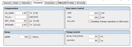
Now I am using TPS53679RSB and CSD95490Q5MC to build two channels output VRMs (12V input, channel A 2phase for 0.9V/65A output + channel B 2phase for 3.3V/40A output). In the application, SVID and DC load line are disabled. And under controller TPS53679 phase, inductor, output capacitors (especial for all ceramic output capacitors) are determined, is there any simple method to compute digital compensation parameters (AC_GAIN, AC_LL, INT_Time, INTGAIN and even RAMP, etc) illustated below to ensure power supply stability (loop phase margin), for example with some formula, excel or GUI auto tune functions? For all ceramic output capacitors, what should I pay attention to? And could you give some advice?

In additon, I would like to simulation the VRMs described above, and how to simulate it, could you give some recommends? And how to adjust the digital loop (parameters)? Could you supply the devices (TPS53679RSB and CSD95490Q5MC) model? And how to change digital compensation parameters in simulation tool, for example in PSpice tool?

  • Hi 

    The member supporting this is OOO until next Monday and please expect a response next week.

    Regards

    Yihe 

  • Hi John,

    We do not have direct simple calculation or equation  to compute the compensation parameters. However below is a brief overview about it

    • AC_GAIN, lowering it helps with increased transient stability but at the cost of transient speed. Increasing it accelerates transient response.
    • AC_LL, Lowering it will help with a faster transient response and less phase margin, but lowering it too much may lead to loop instability. Increasing it will have the opposite effect. 
    • INT_Time, it helps with settle time during transient response. Decreasing it will give you a faster settle time
    • INTGAIN, it set the gain in integral path.
    • RAMP, it helps with jitter and ripple performance. Lowering it will lower your transient response but will help with jitter and ripple

    The ceramic capacitors will derate its value as voltage increases, please refer the manufacturer datasheet or website for derating details. It is always recommend to use with voltage rating of 2 time of peak output voltage.

    We do not have a pspice model for these devices, but we have SIMPLIS model, Please let me know if you need it.

    Regards,

    Shamveel