Tool/software:
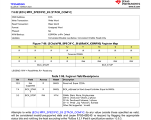
i am using TPS546D24S for 2 phase stacking. i have made changes based on the datasheet. i am doing configuration for controller and follower by using PMBUS communication. the configuration for controller and follower for stack config , interleave is as follows
controller
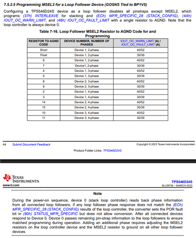
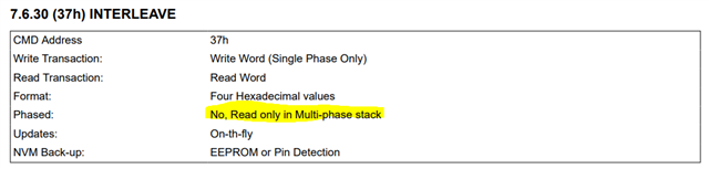
interleave - 0x0020
stack config - 0x0001
Follower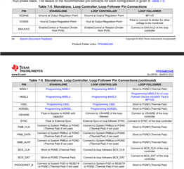
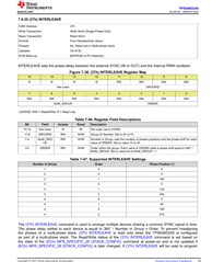
interleave - 0x0021
stack config - 0x0001
as i read the datasheet it is mentioned that other configuration follower will take from controller. and i have changed the address of follower as well to 0x01. my issue is i am getting bcx error what could be the possible reason any other register i need to configure. Thanks in advance for any help