This thread has been locked.

If you have a related question, please click the "Ask a related question" button in the top right corner. The newly created question will be automatically linked to this question.

BQ25756: Setting of CV Timer

Part Number: BQ25756
Other Parts Discussed in Thread: TPS26750, , BQ25751

Tool/software:

Hi,

I use TPS26750 & BQ25756 for charging and discharging 14s Li-ion battery on USB-C PD3.1 240W(48V/5A) sysytem.
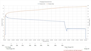
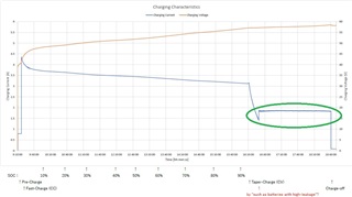
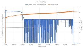
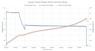
When charging the battery,CV mode start from 3.1A(CC mode),but CV mode changes to CC mode(1.8A) at 1.5A
(setting of termination current is 0.3A).

I suspect that the cause is the high leakage current of the battery as stated in BQ25756 datasheet(8.3.4.6 CV Timer).
So I want to try to change the setting of the "CV_TMR" register from disable to 3hr.

I am writing the binary data created using online configration tool to the EEPROM.
There are no settings in the online configuration tool, and there doesn't appear to be any settings in the binary data in the EEPROM
(Address:0x0AFC-0x0BFB, 0x46FC-0x47FB).
Is there any way to set this register?

Regards,

Ken18

  • Hello,

    Thanks for being patient with this. I'll get back to early next week on this question.

    Best Regards,
    Ethan Galloway

  • Hello Ken18,

    Once again, thanks for being patient with this.

    The CV_TMR is not available on the BQ25756. That register is meant for the BQ25751 which charges lead acid batteries.

    I have a few questions and suggestions to help us debug this:

    • To improve charging accuracy, is EN_PFM=0? Setting EN_PFM=0 will improve termination accuracy when the current is less than 2A.
    • Do you know what the registers of the BQ25756 are during this state?
    • If possible, do you know what the status registers of the battery gauge/monitor are?

    Best Regards,
    Ethan Galloway

  • Hi Ethan Galloway,

    First of all, if the CV_TMR is not available, why is it listed in the BQ25756 datasheet(I2C Register Address = 0x16)?

    > To improve charging accuracy, is EN_PFM=0?
    I have tried setting EN_PFM = 0, but VBUS remained at 5V and did not rise to 48V, so it was NG.
    (binary data of EEPROM has been changed as follows:
        Address                                            from                     to
        0x0AFC-0x0B00,0x46FC-0x4700    0x7B62011920    0x7B62011900
    or 0x0B59-0x0B5D,0x4759-0x475D    0x9062011920    0x9062011900
    or 0x0B9C-0x0BA0,0x479C-0x47A0   0x9662011960    0x9662011940
    or 0x0BD0-0x0BD4,0x47D0-0x47D4   0x2462011960    0x2462011940
    or 0x0BE6-0x0BEA,0x47E6-0x47EA   0x5C62011960    0x5C62011940)

    > Do you know what the registers of the BQ25756 are during this state?
    It remains CHARGE_STAT[2:0]=Taper Charge(CV mode)[100b].

    > If possible, do you know what the status registers of the battery gauge/monitor are?
    I don't know what "the status registers of the battery gauge/monitor" refers to.
    Can you please explain it more specifically?

    Best Regards,
    Ken18

  • Hello Ken18,

    First of all, if the CV_TMR is not available, why is it listed in the BQ25756 datasheet(I2C Register Address = 0x16)?

    Thanks for being patient with this. I'm working on fixing this.

    To disable charging after a certain amount of time, you can set the safety timer with the bits EN_CHG_TMR and CHG_TMR.

    > If possible, do you know what the status registers of the battery gauge/monitor are?
    I don't know what "the status registers of the battery gauge/monitor" refers to.
    Can you please explain it more specifically

    Does the 14s battery in the circuit have it's own memory or registers? If so, is the 14s battery terminating charge correctly? Generally, the battery's termination current should be above the charger's termination current setting.

    Best Regards,
    Ethan Galloway

  • Hi Ethan Galloway,

    > To disable charging after a certain amount of time, you can set the safety timer with the bits EN_CHG_TMR and CHG_TMR.

    Since Charge off occurs approximately 9.5 hours after Fast-Charge, I think there is no need to change the Safety Timer
    from its default value of 12 hours.


    > Does the 14s battery in the circuit have it's own memory or registers? If so, is the 14s battery terminating charge correctly? Generally, the battery's termination current should be above the charger's termination current setting.

    The SOC on the charging characteristics graph is the value read from 14s battery, and the charging turns off before the SOC reaches 100%.
    As a test, I tried to increase the voltage from 57.4V(the nominal value of this battery) to 58.8V(4.4Vx14, the common value for a 14s battery)
    by changing the FB resistor, but the SOC did not reach 100% and an error occurred inside the battery at 58.9V(overcharging?),
    and the battery would not start up after that.
    The nominal cutoff current for this battery is 0.3A, so the Termination Current is also set to 0.3A.

    Best Regards,
    Ken18

  • Hello Ken18,

    Thanks for the new information.

    Can you summarize the current issues you are facing?

    To get the battery to reach 100% SOC, you may need to adjust the registers of the battery monitor/gauge. Do you know the battery monitor/gauge? You may be able to reach out to its manufacturer for help.

    Also, if the charger still isn't behaving correctly, can you send me the schematic?

    Best Regards,
    Ethan Galloway

  • Hi Ethan Galloway,

    > To get the battery to reach 100% SOC, you may need to adjust the registers of the battery monitor/gauge.
    > Do you know the battery monitor/gauge? You may be able to reach out to its manufacturer for help.

    I don't think it's necessary to reach 100% SOC.
    Regarding the battery, only reading the status register via CAN communication has been disclosed to us.
    The problem is that the charging current during Taper-Charge doesn't drop to the termination current,
    but becomes a constant current halfway through.
    (The part in the green frame in the charging graph below.)


    IF this charging process is normal, then there's no problem.

    > Also, if the charger still isn't behaving correctly, can you send me the schematic?

    I don't want to make the circuit diagram public, what should I do?
    I can disclose it only to you.


    By the way, I can read the I2C data from BQ25756, but the data I wrote is not reflected when I read it back.
    Is there any kind of protection function against writing?

    Best Regards,
    Ken18

  • Hello Kenzo,

    Thanks for being patient with this.

    IF this charging process is normal, then there's no problem.

    This charging process is not normal and I haven't seen this problem before. I think the battery's circuits might be messing with the charge process here.

    I've got a few questions for the information in the green frame:

    • Is the battery voltage still rising while the charger is in taper charge?
    • Can you measure the voltage on the VFB pin while the charger is in taper charge? Make sure the charger is off before you connect the probes to VFB. VFB is susceptible to interference when probes are connected to it.

    > Also, if the charger still isn't behaving correctly, can you send me the schematic?

    I don't want to make the circuit diagram public, what should I do?
    I can disclose it only to you.

    Can you send the schematic over E2E's direct message?

    By the way, I can read the I2C data from BQ25756, but the data I wrote is not reflected when I read it back.
    Is there any kind of protection function against writing?

    Some of the registers of the BQ25756 are protected against writing. What registers and bits are you trying to write too?

    Best Regards,
    Ethan Galloway

  • Hi Ethan Galloway,

    > I think the battery's circuits might be messing with the charge process here.

    I have contacted the battery manufacturer about this issue and whether there are any settings that need to be made when charging.


    About the information in the green frame
     > Is the battery voltage still rising while the charger is in taper charge?

     As can be seen from the graph, the battery voltage(=charging voltage) continue to rise until charge termination.

     > Can you measure the voltage on the VFB pin while the charger is in taper charge?

     Please refer to the graph below.
     Since the VFB pin is directly connected to the logger input(input resistance=1M), this is likely to be different from the actual operation.


    > Can you send the schematic over E2E's direct message?

    Please tell me how to use E2E's direct message.


    > Some of the registers of the BQ25756 are protected against writing. What registers and bits are you trying to write too?

    I have tried to write CV_TMR only.
    Since CHG_TMR could be rewritten, it means CV_TMR is protected?


    Best Regards,
    Ken18

  • Hello Ken18,

    Thanks for the new information. I think there might be an IR drop from the feedback resistor network to the battery. The FP pin voltage seems to be stable while the battery voltage rises. Can you measure the voltage from the output of the charger to the battery terminals? A voltage drop here will extend the amount of time the BQ25756 spends in the constant voltage phase.

    Please tell me how to use E2E's direct message.

    I sent you a connection request over E2E. Once we are friends on E2E, you can then directly message the schematics to me.

    Since CHG_TMR could be rewritten, it means CV_TMR is protected?

    I think these bits are write protected. Let me confirm this and get back to you.

    Best Regards,
    Ethan Galloway

  • Hi Ethan Galloway,

    > Can you measure the voltage from the output of the charger to the battery terminals?

    I measured the output voltage of the charger and the terminal voltage of the battery.
    I have confirmed that the same display is shown at the same measurement point for each logger input channel.
    This voltage difference is likely due to the resistance of the connector(CN3) and connecting wires(AWG18_50mm x 2).


    Best Regards,
    Ken18

  • Hello Ken18,

    Thanks for sending me your schematic. I replied back to you over there.

    It looks like there's a voltage drop of 0.1V from the charger's output to the batteries terminal. This voltage drop might be hard to tell because of the graph, though.

    I've got a few more questions to help us debug this:

    • How long are the wires from the charger to the battery? What's the ESR of the battery?
    • Can you use a dedicated voltage meter to measure the voltage drop from the charger to the battery while fast charge mode?
    • Can you measure the VFB pin with a dedicated voltage meter or oscilloscope to see if there is noise on this pin?

    Best Regards,
    Ethan Galloway

  • Hi Ethan Galloway,

     While looking back at past documents regarding the ESR of the battery, I noticed that there is a charge standby mode among the state transitions.
    Our company has only ever used this battery in discharge mode, so we overlooked this.
    Currently the battery is being charged in the state of discharge mode, so it seems that it will be necessary to switch to chargie standby mode before charging.
    We are expecting a response from the battery manufacturer next week, so we will take that into consideration and confirm the matter again.


    > How long are the wires from the charger to the battery? What's the ESR of the battery?

    As I mentioned in my previous reply, the wiring from the charger to the battery is 50mm long, and AWG18 is used for the PACK+/- wiring.


    > Can you use a dedicated voltage meter to measure the voltage drop from the charger to the battery while fast charge mode?

    I plan to measure this if the issue persists even after putting the battery into charging standby mode for the reasons mentioned above.


    > Can you measure the VFB pin with a dedicated voltage meter or oscilloscope to see if there is noise on this pin?

    Please refer to the diagram below.


    Best Regards,
    Ken18

  • Hello Ken18,

    Thanks for the new information. Let me know if the circuit works with the battery manufacturer's suggestions.

    The noise on the FB pin is strange. You may be able to improve this behavior by installing a 100pF filter capacitor in parallel with the top battery feedback resistor (R3,R9,R13).

    Best Regards,
    Ethan Galloway

  • Hi Ethan Galloway,

    I received a response from the battery manufacturer, and they told me that the charging format is not CC/CV, but 4-stage CC charging.
    The required charging current is calculated form the maximum cell voltage, so the charging current needs to be changed accordingly.

    So I would like to confirm, is there any way to prevent charging from entering CV mode other than by increasing the voltage at the FB pin?
    I think the charging current can be controlled with ICHG_REG, but to end charging, is it enough to disable EN_CHG?

    Best Regards,
    Ken18

  • Hello Kenzo,

    Thanks for the new information.

    What is 4 stage CC charging? Did the battery manufacturer provide a recommended charging current profile? 3-stage or 4-stage charging is usually used for lead-acid batteries.

    If you need 3-stage charging, the BQ25751 is a dedicated 3-stage lead acid battery charger.

    So I would like to confirm, is there any way to prevent charging from entering CV mode other than by increasing the voltage at the FB pin?
    I think the charging current can be controlled with ICHG_REG, but to end charging, is it enough to disable EN_CHG?

    I'm not quite sure what the system goal is here. Why does the battery charger need to be prevented from going into CV mode?

    To prevent the IC from going into CV mode, you can set the termination current to just below the fast charge current. With this setup, the IC will stop charging the moment that the battery voltage stabilizes and the fast charge current drops.

    Best Regards,
    Ethan Galloway

  • Hi Ethan Galloway,

    A new version of "USBCPD Application Customization Tool(1.1.0)" has been uploaded, so I tried using it and found that this problem was fixed.
    In CV mode, the charging current drops to the charging termination current value and charging stops.
    I had been using version 1.0.2 until now, so I wonder if there had been any related changes?

    Thank you very much for all your support.
    I think I can manage the rest.

    Best Regards,
    Ken18

  • Hello Ken18,

    Thanks. I'm glad to hear your problem was fixed.

    Let me loop in the USB-PD experts for this question.

    Best Regards,
    Ethan Galloway

  • Hi Ken18,

    As Ethan mentioned earlier, if EN_PFM is set and I_term is <2-A, the current is not regulated well. The latest GUI disables EN_PFM while v1.0.2 was previously setting it. This is likely why the behavior improved.

    Thanks and Regards,

    Chris

  • Hi Chris,

    Thanks for your information.
    I Understood it.

    Best Regards,
    Ken 18

  • Hi Ken 18,

    You're welcome, closing this thread now.

    Please open a new thread if you have any new questions.

    Thanks and Regards,

    Chris