This thread has been locked.

If you have a related question, please click the "Ask a related question" button in the top right corner. The newly created question will be automatically linked to this question.

TPS25830A-Q1: USB 3.2 design/layout guidelines?

Part Number: TPS25830A-Q1
Other Parts Discussed in Thread: TUSB542

Tool/software:

Hi Team,

Do we have an app note or any collateral involving a design or layout guidelines for USB 3.2? I've found some collateral for high speed interfaces, but not specifically USB3.2. Thanks in advance!

Best,

Jason Maxwell

  • Hello Jason,

    Which USB3 redriver/MUX will be used with the TPS25830A-Q1 for USB 3.2 communication?

    The TI doc that I always refer to is the High-Speed Layout Guidelines for Signal Conditioners and USB Hubs Application Report here. The table under Section 2.2 must be followed for the USB 3.x protocol. And there are very informative layout guidelines throughout this doc. 

    After going through this doc, please let me know if you have any additional questions.

    Thank you and best regards,

    Seong

  • Hi Seong,

    Thank you for the information! I believe that they are using the TUSB542RWQR for the redriver/MUX. I will send this information over and let you know if there are any follow up questions.

    Best,

    Jason

  • Hi Jason,

    I am happy to help.

    Please see Section 10.3.16.5 in the TPS25830A-Q1 datasheet for details on how the POL pin can be used to control the TUSB542's SEL pin. 

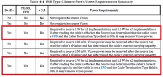
    Also, Table 4-4 from the USB Type-C Spec R2.4 shows that VCONN must source 1W VCONN for single-lane USB 3.2 and 1.5W for dual-lane USB 3.2 communication. 

    As stated in Section 10.3.5 VCC, VCC_UVLO of the TPS25830A-Q1 datasheet, "In applications where VCONN support is required, the VCC pin can be over-driven with an external 5-V LDO capable of sourcing at least 300 mA. In this operating mode the external LDO is the source for the buck low-side switch gate drive as well as power to the internal VCONN mux.

    Note if using external 5-V LDO for VCONN power, the timing sequence below must be required. External VCONN power can not be enabled before the TPS2583xA-Q1 is enabled, external VCONN must be disabled before the TPS2583xA-Q1 is disabled. In a real application, customer can tie the EN of external 5-V LDO and EN of TPS2583xA-Q1 together to meet the timing requirement." 

    However, despite the USB Type-C specification, I have supported customers who have reported that USB 3 communication was successful without externally driving the VCC pin to source 1W or 1.5W VCONN. If the customer is building an evaluation board, please advise they add provisions for an external LDO to test with and without an external 5V 300mA source.

    I will move this thread to the HSC bucket, so the team supporting the TUSB542 device can further assist with USB 3.2 design/layout guidelines.

    Thank you and best regards,

    Seong