This thread has been locked.

If you have a related question, please click the "Ask a related question" button in the top right corner. The newly created question will be automatically linked to this question.

LM117: LM117

Part Number: LM117
Other Parts Discussed in Thread: LM317

Tool/software:

Hello,

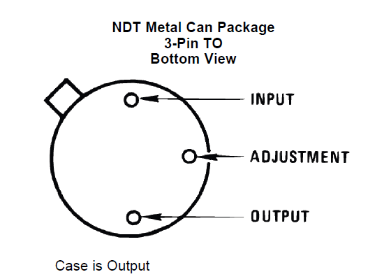
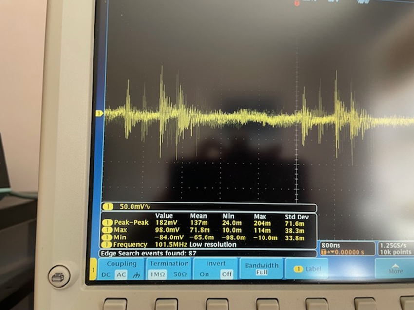
I am using the lm117 to generate a 2V rail, however, its output contains a lot of a.c. noise as shown below:

schematic is

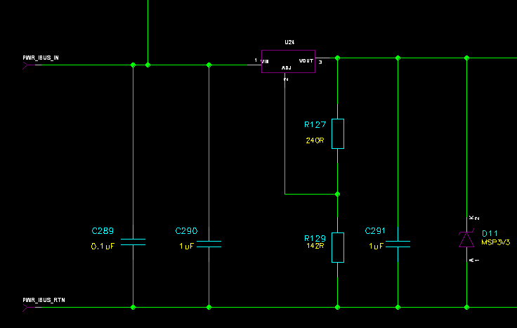
I have added 220uF caps to both the input and output as well as a 10uF bypass across the ADJ pin, but the output is very noisy as shown above: the repercussion is that decoupling capacitors around the load are getting hot because the latter's ESR is being affected by the a.c. ripple riding on the 2V d.c. rail.

Is the above noise magnitude expected and how can I reduce it?

Thank you

  • Hi Rajan,

    The noise shown in your oscilloscope shot above is extremely high frequency (I count 7 cycles in 1ns, or 7GHz) - well beyond the bandwidth where the LM117 can effectively filter it. Given the frequencies in question, I suspect ambient noise coupling into the measurement setup. Large loop areas in oscilloscope ground clips can easily couple external noise in.

    If the noise isn't a measurement artifact, I'd recommend adding additional small decoupling capacitors (1nF or so) with very high self-resonant frequency as close as possible to the source of the high-frequency noise. 

    Regarding the capacitor temperature increase, I think it is unlikely that the ripple seen here will cause significant heating of the capacitor. It is possible that a cracked ceramic capacitor could have failed to a low-resistance short, significantly increasing its power dissipation, but this will not be a frequency-dependent behavior.

    Best Regards,

    Alex Davis

  • Hi Alex,

    I used a very high-specification 8 GHz scope and a 9 GHz probe with the latter soldered directly across the output ceramic capacitor, i.e. there was no large loop area!

    Ceramic caps heat when their internal ESR receive excessive a.c. ripple current: if the LM117 is disabled, the caps do not glow warm, only when the LM117 is functioning. This means ripple from the regulator is impacting the ESR.

    Given the capacitor values I am using in the schematic below, as well as the 220uFs I added to the input and output, is there any change the LM117 could be unstable, therefore, not settling to a steady d.c. value? How could I check for this?

    Thank you and kind regards,

    Rajan

  • The other reason I am suggesting stability is the LM117 is very hot even though its load current is around 300mA, I've burnt myself several times!

    I'm using the following package:

  • here's a representative picture of how I directly solder the scope probe to the test point:

  • Alex,

    I repeated the measurements using a 500 MHz Tektronix scope and the results differ: both ac and dc coupling plots are shown below:

    What are you comments?

    Rajan.

  • Hi Rajan,

    Your described probing method is sound - it looks like the image didn't attach, but a soldered connection across one of the capacitors will, indeed, be about as minimal loop area as possible. 

    Can you measure input current to the LM117? What is your input voltage in this application? 

    Assuming a 5V input and 300mA of load current, power dissipation in the LM117 would be 900mW. The NDT package has an RθJA of 186°C/W, so 900mW would result in a 192°C junction temperature (assuming 25°C ambient, and no heatsink). That's well above the maximum junction temperature and would likely result in the device entering thermal shutdown. 

    From the output ripple measurements, this doesn't appear to be a stability issue with the LM117, at least at first glance. Bandwidth for a device like the LM117 should be in the 1-100kHz range, and I'd expect a stability issue to show up as an oscillation or ringing in that band. The 10MHz+ tones in your latest scope capture are well outside that range. 

    Capacitor self-heating due to ripple is possible, but the ripple seen here appears too small to produce significant heating. I pulled a Murata simulation model for their GRM153B30J104ME15 1µF, 6.3V ceramic capacitor and ran some quick simulations.

    The largest peak-to-peak swing I see in your capture above is ~200mVpp, or ~71mVrms. The peak power dissipation in the ESR of the GRM153 is about 250mW at about 11MHz. That assumes a continuous 200mVpp tone, however.

    Using a more conservative 100mVpp continuous amplitude from your first oscilloscope capture, the power dissipation drops to about 60mW max at 11MHz. An increase in ESR would decrease this power dissipation, assuming capacitance stays constant. 

    If only one or two capacitors are overheating during operation, I'd still suspect mechanical damage to the capacitor itself. Cracked ceramic capacitors tend to fail low-resistance, which would increase current consumption from the LDO and result in increased heating of the LDO and capacitor.

    Best Regards,

    Alex Davis

  • The input voltage to the LM117 is +5V which means PD = 3 * 0.3 = 0.9W which is within specification, but as you say, a heatsink is required at ambient for reliable operation. I note your comment about the cracked capacitors, however, identical heating was observed on both hardware builds.

    Is the max. power rating of the LM117 in the NDT can package 2W?

    Regards,

    Rajan

  • can you recommend a small heatsink I could attach to the lm117 can package please?

  • Hi Rajan,

    Max power dissipation depends on thermal resistance and ambient temperature in order to not exceed the max recommended junction temperature of 150°C. 

    Assuming a 25°C ambient temperature, and choosing a 120°C junction temperature to give plenty of margin, the thermal resistance from the junction to the ambient air needs to be (120°C - 25°C) / (0.9W) = 105°C/W. The Junction to Case thermal resistance for the LM117 TO-CAN package is 21°C/W, so you'll need a heatsink with a thermal resistance of 84°C/W or lower. 

    I'd suggest any of the following Boyd Laconia part numbers:

    325705B00000G

    322505B00000G

    311505B00000G

    578305B00000G

    Regarding capacitor cracking, board flex during assembly can cause cracking in more than a single board. I saw a case where a large ceramic capacitor placed near a board edge cracked in 30% of assemblies due to stress when handling tabs were removed from the PCB. I have heard, but haven't personally seen, of cracking due to thermal shock during soldering if excessive heat is concentrated on the capacitor terminals as well. 

    If only one or two identical or near-identical capacitors on the same net are heating up, and those are placed near stress concentrators such as mounting hardware, connectors with high insertion force, or board edges where handling tabs were removed after assembly, I would suggest removing and replacing those capacitors. 

    Best Regards,

    Alex Davis

  • the 2 to 3 caps are in the centre of the board as shown below:

    there are no stress concentrators in this area.

    thank you recommending heatsinks for the lm117, can you also recommend ones for the lm317 please.

    I have removed the electrolytic caps from the board as these will have large ESR which will increase ripple.

    kind Regards,

    Rajan.

  • Hi Rajan,

    Which package of LM317 are you using? 

    I'd recommend replacing the hotspot capacitor at the right side of the board - for it to get that hot suggests damage to me, rather than AC power dissipation. 

    Best Regards,

    Alex Davis

  • The caps don't glow when the lm117 is disable, only when active which sort of suggests the caps are not damaged - what do you think?

  • the lm317 is in a NDE0003B leaded package

  • feedback from assembly sub-contractor:

    I believe these are 0603 capacitors.

    There’s nothing unusual about them, they are a standard part.

    There would have been no difficulty fitting these parts.

    They are hand placed in to solder paste and vapour phase reflowed.

  • If the capacitor has been damaged, and is shorted (or low resistance) internally, and is connected to the output of the LM117, then the DC short will only be powered when the LM117 is enabled - similar to how a resistor on the LM117 output will only dissipate power if the LM117 is enabled.

  • Hi Rajan,

    Heatsink selection for the LM317 will depend on power dissipation as well. If LDO dissipation is less than about 4W and ambient temperature doesn't exceed 25° the LM317 NDE may not require a heatsink. 

    If you anticipate power dissipation closer to 10W, the LM317 will need a heatsink with a thermal resistance less than about 8°C/W. A Same Sky HSS01-B20-CP may work in this application.

    Regarding the capacitor power dissipation, I have a few measurements to try:

    • Make a DMM resistance measurement on your 2.0V supply on an unpowered board. Low DC resistance on an unpowered PCB may not be totally conclusive, especially for supply rails powering large amounts of digital logic (FPGA supplies, for example, can appear as short circuits when unpowered even if no short circuit exists). For lightly loaded analog supplies, I'd generally expect to see a fairly high impedance (kΩs or more) often showing significant fluctuation over time as capacitors charge. 
    • Make an oscilloscope measurement of current into the LM317, both at low frequency (<1MHz) and higher frequency (~100MHz) if possible. A large amount of current ripple here might point towards a stability issue if one exists. Again, this may not be conclusive if your 2.0V loads exhibit significant current swings. 
    • Replace the hot capacitor. I understand that the likelihood of damage there seems low, but if you have access to soldering equipment, it is an easy and inexpensive test to rule out that possibility. 


    Best Regards,

    Alex Davis