This thread has been locked.

If you have a related question, please click the "Ask a related question" button in the top right corner. The newly created question will be automatically linked to this question.

UCC28951: High losses in shim inductor

Part Number: UCC28951

Tool/software:

Hi,
I have designed a psfb dcdc converter 800V in, 120Vout,  600W. I've calculated the need for 40uH shim inductor. Transformer magnetizing inductance is about 6mH and leakage is about 11uH.

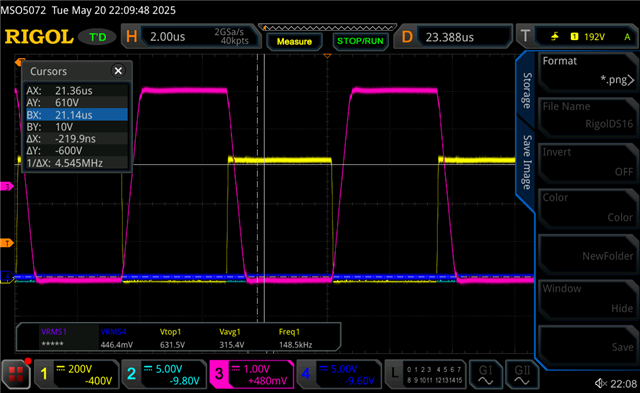
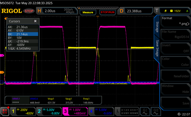
All works fine except the shim gets very hot. It seems I get very high voltage over the shim and saturate the core, which I didn't expect. To avoid this I need a physically very large inductor which is impractical.

Is this reasonable?

  • Hello,


    If your inductor is getting hot you are using and inductor with too much DCR or your inductor is Saturating.  I would suggest that you select an inductor with higher saturation current and/or lower DCR until you get one that does not dissipate as much power.


    Regards,

  • Thanks for your reply Mark,
    I've tried many different inductors, both off-the-shelf and self-made. For some I get copper losses (DCR and others, I run at 150kHz) and/or core loss. The only way to mitigate this is with a quite physically large inductor to reduce B in the core. I would be ok with this (although impractical) but since it needs to be very much larger than what is used in the PWR551A evk, I think I'm doing something else wrong. The main thing that confuses me is the voltage across the shim. It looks like I get the full input swing over the shim. I was expecting voltage division between shim and transformer magnetizing inductance, which would give me much less. At 800V (or about 400Vrms) over the shim I will indeed need a large low u core for this application. 
    For example. For the output inductor (150uH) I use a PQ35/35DG core and I get no heating at all att full power. The same core and wire awg (but reduced to 40-100uH) on the shim I get high core loss.

    Is this expected or am I doning something else wrong?

  • Hi Jesper,

    If you are getting full voltage across the shim inductor, it can be also because of transformer saturation.

    I need some more details for supporting your issue.

    Can you share the waveforms of shim inductor voltage and transformer voltage along with transformer current?

    Can you also confirm whether you are using primary side diode clamping or not?

    Regards,
    Deepak K

  • Hi Deepak,
    The transformer is not saturating, and I confirm I have primary side clamping. I have full voltage over the shim, but only briefly. ET of the inductor needs to be >200Vus or so. After designing an inductor with that in mind, as well as max current, it behaves a bit better, but still overheats a bit. However, my shim/transformer current looks a bit weird, and I think secondary rectifier fet timing is off. I will evaluate that further tomorrow and If I still have issues I'll get back with more info/graps/questions.

    BR Jesper

  • Hi Jesper,

    Sure, thanks for the update. 

    You can reach out after the debug steps and still the problem is not solved.

    Regards,
    Deepak K

  • Hi,

    I still have issue with shim getting very hot, even though it is now more than enough designed for the task. It is by far the warmest part in the design.

    Here are some plots of shim-current and shim-voltage on both sides of the shim. Measured at about 50% power. Input voltage to Hbridege is 660V in this case. Shim about 50uH. The current does not look as I would expect from the documentation.

    The voltage after the shim is shifted 300ns or so and there's some wiggle. Current is 1A per 1V. Sorry for the cursors not being relevant. Also realize the current is inverted, but you get the idea..


    BR Jesper

  • Hi Jesper,

    Thanks for sharing the waveforms.

    Can you please help me understanding the waveforms?

    What are the difference between 1st and 2nd figure you shared?

    As I understand it, Ch3 is the shim inductor current and Ch1 is the voltage across shim inductor, please confirm the same.

    It would be better if you can show following waveforms.

    • Voltage across the shim inductor
    • Current through the shim inductor
    • Primary side transformer voltage
    • Current through the transformer

    These waveforms should give us a better picture of the issue. 

    Regards,
    Deepak K

  • Hi Deepak,

    Ch3 is current through shim, in both cases. Ch1 in the first picture is voltage before shim. Ch1 in the second picture is voltage after shim, at the transformer.
    The voltage is very similar, just phase shifted and with some wiggle.

    I cannot make more measurements at the moment, my bench PSU had a catastrophic failure..

    BR Jesper

  • Hi Jesper,

    I Understand. Thanks for sharing the waveform details.

    The shim inductor current waveforms are flat which is not expected during the ON time period of the converter. The current waveform should be flat during freewheeling time and during clamping diode conduction time. After clamping diode stops conducting, the shim inductor current will ramp up. Here I am not able to differentiate between the free wheeling and ON time period of the converter. Still based on the given information, it looks like clamping diodes are conducting throughout the switching cycle. This can be due to transformer peak current is smaller than the shim inductor freewheeling current. It is better if you can capture the waveforms I mentioned in my previous response. Those waveform will help in arriving in some conclusions.

    I will wait for you to repair and power up the board again.

    Regards,

    Deepak K

  • Hi Deepak,

    When you say "during clamping diode conduction" do you mean the primary side clamping diodes between the shim and transformer? These also get hot, so it seems right that they are conducting too much. 
    I have received a new bench PSU and will do more measurements when I'm back at the lab on Monday.

    BR Jesper

  • Hi Jesper,

    Yes, I was referring to primary side clamping diode connected between shim inductor and transformer. If diode is conducting for longer period, it can be because of high forward recovery time of the diode. So, if the diode is taking time to change state from reverse bias to forward bias, due to the LC oscillation caused by transformer leakage inductance and secondary FET Coss, shim inductor current is going higher than peak current of transformer. Only after this clamping diode starts conducting and end up conducting throughout the ON time due to high freewheeling current. This can be solved by replacing the diode with some fast-reacting diodes. Can you share the part number of the diode you are using?

    We will see the waveforms and confirm this theory once you are ready with the waveforms.

    Regards,
    Deepak K

  • Hi Deepak,

    I'm currently using C4D10120E at this position. I intended to use STTH212S but at some point during bringup I broke these and figured they were too small. I need at least 1kV rated diodes, but wasn't sure about the current req. I have also changed the secondary fets to IXFH34N65X3 which have significantly higher Coss than the IMW120R090M1H that I used previously. I changed to IXFH34N65X3 to get a fet with a faster body diode, in the quest to reduce ringing. 

    BR Jesper

  • Hi Jesper,

    This can be the root cause of the issue you are seeing.

    Anyways, I will wait till you are able to power up and share the waveforms. So that we can confirm this.

    Regards,
    Deepak K

  • Hi Deepak,

    I changed to a lower Coss secondary fet and it seems to have mitigated the issue. Thanks for your support!

    BR Jesper