This thread has been locked.

If you have a related question, please click the "Ask a related question" button in the top right corner. The newly created question will be automatically linked to this question.

TPS25751: adding extra config parameters to EEPROM for BQ charger

Part Number: TPS25751
Other Parts Discussed in Thread: BQ25731,

Tool/software:

I am using a TPS25751S with a BQ25731 charger chip.   I cannot find anything in the USBCPD to add more configuration to the BQ chip other than charge current and charge voltage.  I would like to add more configuration data to be sent to the BQ (the EEPROM must already contain info to be sent to the BQ2731 since charge current and charge voltage data is stored on the EEPROM and written to the BQ from TPS on bootup).  What I am currently in need of is configuring the current sensing resistors for the BQ.  I believe that the default is 5mOhm but I have 10mOhm which is supported, but needs to be configured on the BQ chip via I2C.  There is likely more that I will want to configure on the chip on boot up as well.   I do know that I can use I2C subcommands from my MCU through the TPS25751 to do this, but this seems slow and inefficient (datasheet says 5 seconds per command) and that would be frustratingly slow on boot up for a hardware configuration that won't change.  Other commands I can see wanting are setting up ADCs I would want on the BQ to be available through subcommands of the TPS25751.  Please let me know if there is a way to manipulate the binary for the EEPROM directly, or another USBCPD application tool that has more advanced features to add initialization I2C commands to the EEPROM that will be sent to the BQ25731 chip.  Thanks.

  • Hi John, 

    Thank you for reaching out!

    The TPS25751 controls the registers on the BQ25731 needed to negotiate desired voltage/current. 

    1- Upon power up, the TPS25751 configures the BQ25731 to do the following: 

    • Disable watchdog timer
    • Disable OTG 
    • Disable Charging
    • Set Charge Voltage (based on Q14 in GUI)
    • Set Charge Current (based on Q15)
    • Set OTG Voltage to 5V 
    • Set OTG Current to 950mA

    2- When the PD controller is in a sourcing state, the TPS25751 configures the BQ25731 to: 

    • Enable OTG Mode
    • Set OTG voltage according to the Voltages set in the Source PDOs in Transmit Source Capabilities (Reg0x32 on PD)
    • Set OTG current  according to the currents set in the Source PDOs in Transmit Source Capabilities (Reg0x32 on PD)

    Note: The OTG voltage/current are dynamically changed based on the PDO negotiated (5V --> 9V --> 15V --> 20V-->15V-->9V-->5V for example)

    3- When the PD controller in a sinking state, the TPS25751 configures the BQ25731 to:

    • Set the following parameters according to the user input in the GUI questionnaire:
      • Input voltage limit (VIINDPM) based on Q13 
      • Input current limit (IINDPM) based on Q12 and Active PD contract 
    • Enable Charge 

    4- During voltage transitions, the PD configures the battery charger to safely discharge 

    5- Upon detach or hard reset, the PD configures the battery charger to disable OTG/Charging modes. 

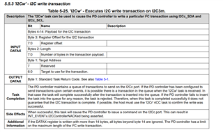
    In general, there should not be a need to do further control as the necessary control is driven from the PD controller. Just to clarify, if your system requires further control of the battery charger, the MCU would need to write to the battery charger through the PD controller using a 4CC command 'I2Cw'. It is not required to wait 5s between I2C writes, this is only a recommendation and understand that it is not feasible in most systems. 

    In regards to the sense resistor, the charge current and input current limit calculations configured by the TPS25751 are based on the default 5mOhm sense resistor and will set those register values accordingly. Unfortunately, we do not have a method currently to calculate based off of a 10mOhm. 

    Please let me know if you have additional questions/concerns. 

    Best Regards, 

    Aya Khedr 

  • Hello Aya,

    Thanks for the response.  In summary, the TPS writes to the BQ every time it is a sinking state, and not on initial boot up.  Is that correct?   This means that the only way to update the registers on the BQ is the 4CC commands and update register 0x31 to change bits 2 and 3 to 0 to set the sense resistor to 10mOhm.  Am I correct here too?   The technical manual is a very long tedious read for the 4CC commands.  When an I2Cw command has completed do you recommend polling the DATAX register (I think that is 0x09) until it changes or should you poll the command register (0x08 i think) to see that change.  Any advice for efficiently using the 4CC commands to pass I2C through to the BQ and ensure write is complete and ready for another would be very appreciated.

    thanks,

    JT

  • Hi John, 

    In summary, the TPS writes to the BQ every time it is a sinking state, and not on initial boot up.  Is that correct? 

    The TPS writes to the BQ on initial boot up to initialize some settings but also writes to BQ every time a new contract is being negotiated, correct. 

    This means that the only way to update the registers on the BQ is the 4CC commands and update register 0x31 to change bits 2 and 3 to 0 to set the sense resistor to 10mOhm.  Am I correct here too? 

    That would be correct, you would write to BQ through the PD controller 4CC commands. The PD I2C is read-modify-write, so you would need to write the full data to register 0x31. 

    My only concern is that the calculations internal to the PD controller are based on the 5mohm sense resistor. I will need to get back to you on whether updating the BQ register 0x31 is sufficient. I will also get back to you with more information on the 4CC commands by end of week. 

    Best Regards, 

    Aya Khedr 

  • Thanks again.  I did check that changing reg 0x31 to the 10mOhm doesn't actually help it adjust to the proper current.  Seems that I have to know that the current resolution changes from 128mV/bit to 64mV/bit in reg 0x03 (charge current register).  I tried changing this during charging (on the fly) and it will not let me.  This is something I definitely want to do, ie change charge current on the fly if I want a very fast charge or safe charge or need an increase in input current for pass through charging.   This may be getting out of scope of this thread, so if you'd like me to create a new one I'm happy to.   I think I also have a bead on the 4CC commands (your tech ref manual is incorrect on format btw, was painful to figure that out, working examples would be helpful to others), so you don't need to research more.  I'm now more focused on being able to configure things on the BQ during charging/discharging as I mention above.

  • Hi John, 

    I tried changing this during charging (on the fly) and it will not let me.  This is something I definitely want to do, ie change charge current on the fly if I want a very fast charge or safe charge or need an increase in input current for pass through charging. 

    The TPS25751 manages the input current limit based on the negotiated PD contract. For instance, if the current negotiated is 3A, it will set the input current limit to 3A or slightly higher (based on Q12 in GUI). This ensures that the battery does not draw more current than being provided from the far-end. During voltage transitions or power role swaps, the BQ charging is disabled as this is a requirement from PD specification. 

    Is the 10mOhm a hard requirement for your system? 

    Best Regards, 

    Aya Khedr

  • The 10mOhm is what I have on the system now.  I am likely going to change them to 5mOhm since this is just a pain and I don't need the extra resolution.  What I do require is to be able to change some settings of the BQ after PD negotiations.  for example, the battery typically charges at 1.675mA (12.6V for the 3 cells I have).  The PD port negotiates 15V/3A from the PD device charging the battery for up to 45W.  What I end up with is ~21W being pulled (IE 12.6V * 1.675A) due to the 1.675A charge current from the EEPROM config.  But, there is more power available (up to 45W).  The battery can sustain up to ~3A input current at that 12.6V getting closer to that 45W but it degrades the battery quicker over time lowering it's lifespan.  I would like to be able to increase the input current from the set value in the EEPROM (1.675A) on the fly if desired (during charging or after the initial PD negotiation).  I adjusted the registers of the BQ to increase the charge current through the 4CC commands after PD negotiation and during charging and it did not update the values or increase the current.  I can update the BQ register when nothing is attached, but it gets overwritten by the values in the EEPROM on sink (as you mentioned).  I'm guessing that I would have to stop the charging, and do some configuration of the BQ through 4CC commands and then restart charging without having the PD negotiations happen again where the EEPROM would overwrite what I want.  I just don't know what chain of events I'd have to trigger in order to do this.  This is really where I need your expertise.  Thanks.

  • Hi John, 

    Thank you for the additional details. I will get back to you on a recommended sequence by Thursday. 

    Best Regards, 

    Aya Khedr

  • Hello Aya,

    I have not heard from you in a few weeks.  Have you had a chance to look into this?  there are many more questions on working with advanced features of this combination like PPS and other that I also have questions about.  Please let me know what you've discovered about this issue (dynamically updating charge current).

    thanks.

  • Hi John, 

    Apologies for the delay here. 

    The PD controller sets the input current limit (Register 0Fh on BQ) based on the Active PD contract and is dynamically adjusted as needed. For instance, if a 15V/3A contract is negotiated, the input current limit will be set to ~3A (can be set x% higher based on Q12 in GUI). If a 15V/2A contract is negotiated, the input current limit will be set to ~2A. The charge current is set once in Q15 in the GUI. I recommend reaching out to the battery charger team on the best method for setting charge current (can it be set to 3A from the start?). 

    In terms of adjusting the charge current on the fly, here is the flow I suggest: 

    1- Set interrupt event (Register 14h) to be alerted when a new PD contract has been negotiated. 

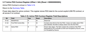
    2- Read Active PDO Contract Register 34h to determine which PDO has been negotiated (for example, a 15V/3A PDO)

    3- Adjust Charge current on BQ to desired value. The Host can write to BQ via 4CC command 'I2Cw'. Note that the input current limit register will be automatically set by the PD controller and does not need to be adjusted by the Host. 

    there are many more questions on working with advanced features of this combination like PPS and other that I also have questions about

    Please post a new thread for questions on new topics for better trackability. 

    Best Regards, 

    Aya Khedr