This thread has been locked.

If you have a related question, please click the "Ask a related question" button in the top right corner. The newly created question will be automatically linked to this question.

Unstable oscillations at switching node in SEPIC configuration

Part Number: LM5158


Tool/software:

I've been studying a SEPIC with reports of frequent failures. The final failure scenario is a short between SW and PGND.


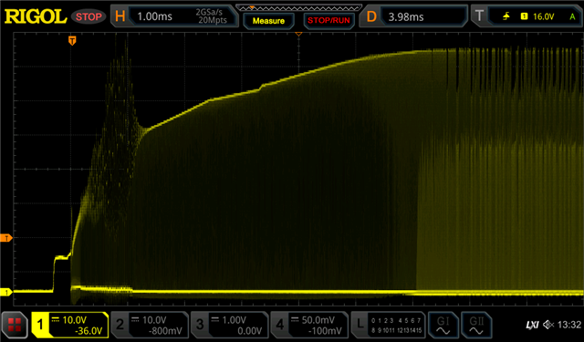
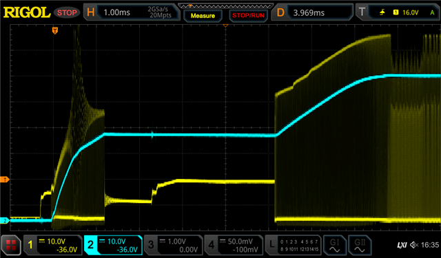
I've confirmed the part choices satisfy the Excel design tool, and in steady state the operation looks good. But I've noticed on some boards there is a repeatable, large oscillation during the soft start.

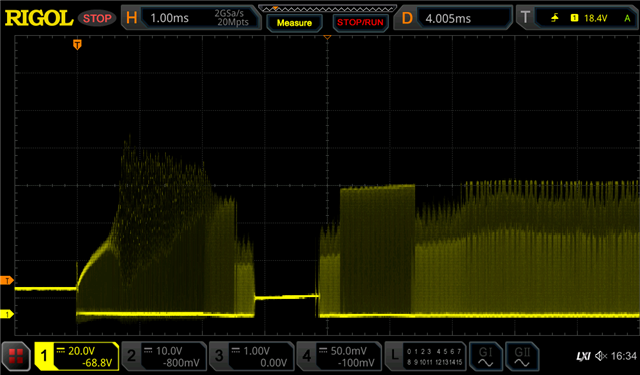
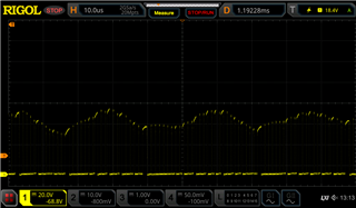
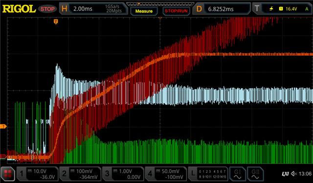
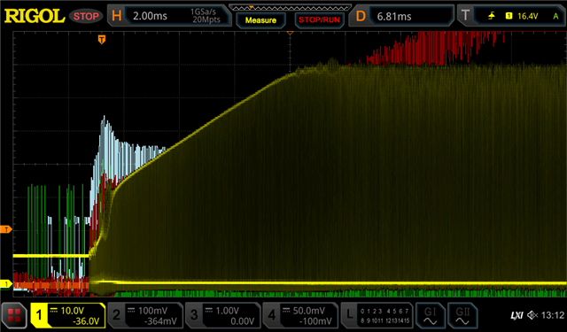
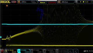
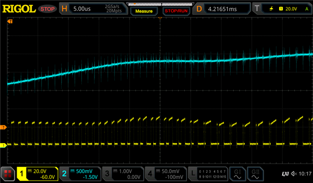
In this case the switching stops and resumes a short time later, everything apparently happy again. The stop period is not always present, but the oscillations are. Here's the start of the oscillation:

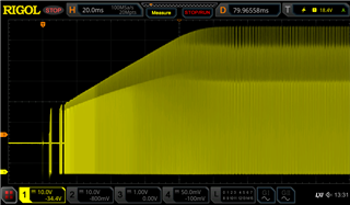
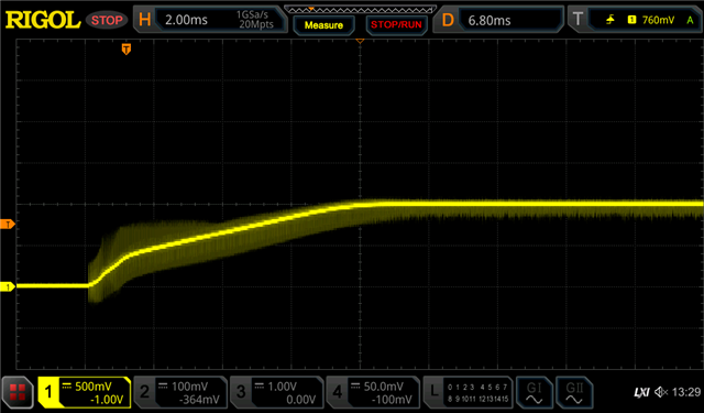
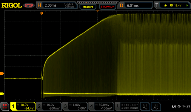
For comparison, here's a "good" (to me) startup, from the same circuit, same layout, but a different part of the board:

The input voltage is 14V and steady. I'm holding the LM5158's EN low and then releasing it when I'm ready to capture the start up event.

The output voltage is 56V. There is no load on it, apart from an idle LTC4263 and its decoupling caps. Although, the input current still rises by 36mA once at steady state. The converter is designed for a 200mA output current.

The switching frequency is set to 915kHz and is effective. During the oscillations I can see the switching duty start varying wildly.

The soft start is set to 10ms, although always seem to start faster than that - between 5ms and 8ms.

Recall that the LM5158's cycle-by-cycle current limit is 3.26A. The inductor's saturation current is 8A.

The max SW voltage is 83V, which is not exceeded in normal operation (14V+56V=70V) but is during these oscillations.


The oscillation frequency is a bit less than 10kHz.


I guess some noise is getting into the feedback loop but the SEPIC characteristics are so complicated I'm having trouble narrowing down potential culprits. I'm wondering:

  1. Is this a known phenomena?
  2. What could be resonating at this frequency? A slightly higher input capacitance and the input inductor? But the switch breaks the loop every cycle. A lower output capacitance and the output inductor? But the diode would have to have meaningful reverse conduction?
  3. With a compensation loop bandwidth of 4.15kHz, should it be attenuating this oscillation and therefore is not working?
  4. Does this look like it could be caused by bad control, or is there something more significant going on?
  • To shine a little more light on the impact of the control loop, I added 100nF to the COMP pin by soldering a 0805 across C_HF (C88). The results are interesting!

    Zoomed in:

    The oscillation is still present at the same point, but amplitude is much less and frequency has doubled!

    The stop period is still present (in fact, on this board it wasn't present before, and is now). But now a new stop period appears. It continues hiccupping like this for ~50ms and then comes good.


    Then I added an extra 1µF on the SS pin (theoretically, making soft start time go from 10ms to 110ms).

    Sure enough, startup time stretches out to at least 100ms, but two other interesting things happen:

    1. The ramp up is highly non linear at first. The jump from ~20V to ~40V (both figures including the 14V Vin) seems to happen all at once.
    2. The switching stops a couple of times - this appears to be pulse skipping, since I can see the duty get very low and the hallmarks of DCM appear (sinusoidal voltage during the off time).

    So I have a wild theory to run by you:

    • With a 10ms soft start time, the initial ramp up is so steep that the inductor saturates / current limit is hit, and the resulting wild current oscillations are too much for the controller to handle. A higher bandwidth control loop might help, but could lead to stability issues. A very slow 100ms soft start time resolves this, at the expense of the ramp beyond 40V being so slow that the controller pulse skips!

    Part of this is motivated by the fact that when I simulated the circuit, I noticed very dramatic current rises during ramp up, and had to ramp up in stages to get the simulation to run in a reasonable amount of time.

  • Hi Heath,

    Thanks for using the E2E forum.

    I will go through your query and will come back to you.

    Best Regards,

    Hassan 

  • Hi Heath,

    Can you please share your Quick start calculator? 

    Best Regards,

    Hassan  

  • Here's the Excel file, but I suspect something will be lost in the round trip through Excel, so I've also attached a screenshot.

    5226.LM5157-58_Excel_Quickstart_Calculator_for_SEPIC.xlsx

  • Hi Heath,

    Thanks for sharing the Excel calculator. I will check and come back to you.

    Best Regards,

    Hassan 

  • Hi Heath,

    Can you try to run the converter without the Hiccup mode?

    Connect the Mode pin to ground

    I just want to see that if the converter is not going into an OCP. 

    Best Regards,

    Hassan  

  • Results are... indeterminate.

    The oscillations don't occur any more if VSYS is steady before releasing EN! I don't know if that's because I added a strap to tie MODE low, or something else has changed in my setup.

    They do still occur if I turn VSYS on without holding EN low. And sometimes the stop period occurs but not always. When it does occur, it looks to me to be more like UVLO than OCP (which may have been the case in my original post too).

    Here's three examples of the oscillation behaviour now that MODE is tied low. Note the different timebase in the third.

  • No surprises here, but just to complete the picture, here's the output voltage in blue at the same time. It's blissfully unaware of the chaos happening at the switching node.

    Accordingly, my experiments to change the compensation values don't seem to have any effect.

  • Hi Heath,

    So according to my understanding, you are saying that the oscillation and stop period only occur when when you turn on the supply while the EN pin is connected to supply via voltage divider and the HICCUP mode is active. 

    But when you turn off the HICCUP mode the issue is not occurring. Am I correct?

    Best Regards,

    Hassan 

  • Not quite. To be accurate:

    The oscillation and stop period now only occur when I turn on the supply while the EN pin is connected to supply via voltage divider. Whether the HICCUP mode is active or not does not seem to matter. The three captures in this post are all with HICCUP disabled (MODE tied low) and the middle one still shows a stop period. After I posted I removed the MODE tie down, and the results didn't change noticeably.

    What changed is that a few days ago I could see oscillation and stop periods even when EN was only released after applying power. When I tried your suggestion, the oscillations were much smaller in that scenario - even on a SMPS that I didn't modify! I don't know what's changed in that time, but this seems to be a marginal effect so it might be a subtle change to my cabling or power supply or something.

    The important thing is these oscillations (and stop periods) still occur, whether MODE is tied low or not.

    If my understanding of HICCUP is accurate, I'm not sure involved here anyway. The datasheet says the off time is 32,768 cycles, which at 915kHz is 36ms. Way longer than anything I've seen here. Besides, the datasheet also says it only applies "after soft start is finished". Although I can't make sense of the last sentence of paragraph 9.3.11, so maybe I don't understand it well. Personally I think the stop periods are more easily explained by either pulse skipping or (sometimes, like in the last capture above where a second SS ramp is evident) UVLO, but it's always good to test these things!

    Anyway, I'm trying not to get tunnel vision, but I noticed the dV/dt during that first steep rise in the blue trace is about 20V in 400µs. With 30µF of output capacitance that's an average output current of 1.5A right? Given the rising output/input ratio and some inductor ripple current, is it plausible I'm hitting the 3.26A limit? I ask because I was studying the wild PWM cycles that occur during these oscillations, and wondered if this is the cycle-by-cycle current limit cutting in. Could the switch node be unstable if the cycle-by-cycle limit is getting hit during soft start?

  • Hi Heath,

    Thanks for the explanation. 

    Can you please send the scope plots of your original hardware setup seen in the shared schematic for COMP, SS, SW, FB and Output signal?

    We will check these signals to give you a correct solution.

    Best Regards,

    Hassan  

  • Okay, sure, but it's difficult to see a lot at this scale in those small signals. Here's all of them except SW:

    • COMP - aqua, 500mV/div
    • SS - red, 200mV/div
    • FB - green, 200mV/div <-- oops, this is MODE, not FB.
    • Output - orange, 10V/div


    And here's with SW overlaid in yellow:

    Note in these captures the oscillation is short lived and not particularly large. But this is the most repeatable behaviour I could muster for the sake of capturing all these signals.

    For a higher res, without the multiple-signal time alignment, but all on the same 500mV/div, 2ms/div scale, here's just COMP:


    and SS:


    and MODE:

    and FB:

  • Addendum

    I wasn't satisfied I was capturing the original event of interest in the shots above, so I continued my search for the conditions that reveal it. After a long search of input voltages, wiring configurations, input capacitance and output capacitance, I happened on a combination that reliably reproduces the original behaviour of concern. So I've reproduced the captures above.

    SW + OUT:

    COMP:

    COMP again, just to be sure:

    SS:

    MODE:

    FB:

    And, just to check SW is still doing what I expect, SW alone:

    Sure enough, there's that damagingly high oscillation right at the knee point of the soft start curve.

    The fact that reproducing this behaviour (which was 100% reproducible in the original board before it succumbed to experimentation!) only came about with a particular tweak to the input capacitance (10µF to 30µF) and the output capacitance (30µF to 60µF) and to the input voltage (12V) and not any more or any less of those variables, leads me to believe there's a narrow band of resonance that is sensitive to parasitics. But susceptible it is.

    I look forward to your advice.

  • Now I have a reproducible case under examination it's easy to capture future insights. Nothing surprising here, but for completeness...

    SW and BIAS:

    SW and anode of diode (note both are 50V/div):

    And a zoomed-in version of above, showing they're just the on/off parts of the oscillation, with the DC offset of the series capacitor. The wild duty cycle changes are evident here too.

  • Hi Heath,

    Thanks you for all the descriptions and detailed waveforms.

    The fact the device stops and starts again should not be a problem. During softstart, the FB pin is regulated to the rising softstart ramp. If VOUT increases faster than the reference ramp, the device will stop switching and waits for the ramp to catch up. This is normal behavior at light loads and not related to overcurrent protection.

    However, the strong oscillation going close to the abs max limit of SW is indeed concerning.
    Just for confirmation, your design uses single inductors, which are not coupled with each other, correct?

    If non-coupled inductor are used, it might be required to add an RC filter in parallel to the coupling capacitor (C81) to avoid oscillation.
    Here is an app note that goes into detail on differences between coupled and uncoupled SEPIC inductors.
    https://www.ti.com/lit/an/slyt411/slyt411.pdf

    Maybe you can check if the resonating frequency you see in your application matches with this formula from the app note?
    Based on the values I see in the schematic, the resonate frequency should be ~35kHz, which could indeed match with the waveforms.


    Best regards,
    Niklas

  • The fact the device stops and starts again should not be a problem. During softstart, the FB pin is regulated to the rising softstart ramp. If VOUT increases faster than the reference ramp, the device will stop switching and waits for the ramp to catch up. This is normal behavior at light loads and not related to overcurrent protection.

    Agreed.

    Just for confirmation, your design uses single inductors, which are not coupled with each other, correct?

    Single inductors. SRP1038A-220M from Bourns Inc, placed next to each other with the series cap between a pair of terminals.

    Maybe you can check if the resonating frequency you see in your application matches with this formula from the app note?

    The oscillation frequency is a bit less than 10kHz. I checked the resonant frequency of all the cap/ind combinations (including the one in the app note) and couldn't find a match! So I figure there's some parasitics at play (possibly capacitance in the internal MOSFET or ESL in the series cap??), but not sure.

    An RC filter is an interesting idea, but at 10kHz I'd be worried it'd be consuming a lot of power.

    Given the dV/dt is abnormally large during this start-up period (the load is no more than 0.2A, yet 1.5A is required to satisfy this dV/dt) I wonder if I'm better off with a solution that only affects soft start. Or do you think there's a concern of stability after ramp up?

  • Hi Heath,

    Thanks for the feedback.

    I was looking at this waveform and checked the distance between the ringing, which looks like in the range of 25us (40kHz) to me.
    This is why I said 35kHz calculated resonance could be a match.

    Maybe you can give a closer estimate here, as you have the waveforms in higher resolution.

    I agree an RC will increase the losses.
    If this oscillation phenomenon only occurs during start-up, you can consider increasing the softstart time immensely, as per you initial testing. I am not fully sure if this solved the issue in all cases, or just reduced the appearance frequency.
    However, this oscillation risk might still be there, so an RC filter seems like a safer option to get rid of this behavior.

    Best regards,
    Niklas

  • Oh I beg your pardon! You're quite right. It is, and always has been, about 39kHz. Thank you very much for checking. I went back through my notes and the only variation on that I can see was an instance where I'd added 100nF to the COMP pin and it was slightly lower, about 35kHz.

    So that resonance could well be a match, which is a big potential clue.

    Your advice on latent oscillation risk is well taken. Proving the absence of a fault is impossible, so I'd like to do what I can to understand its cause, and try to snub out any possibilities of exciting it.

  • I noticed another clue. The emergence of the SW node oscillation coincides with the emergence of the classic sub-harmonic oscillation of the duty cycle.

    Before the SW node oscillation begins, the duty is a steady ~50%. Then as COMP increases, the classic short-long-short-long duty cycle grows and grows until it's around 86% / 8% and all hell breaks loose.

    Here's the emergence of the oscillation. SW in yellow and COMP in cyan.

    Could inadequate slope compensation be a cause all along, and the SW node oscillation be an effect due to inherent resonance??

  • FWIW, my calcs suggest slope compensation is always mathematically adequate, so I don't know what's causing the subharmonic oscillation. To wit:

               Vcomp ≥ (∆Iup + |∆Idown|) x Acs  -- ensure compensation more than the scaled upslope + downslope.
               Vcomp ≥ 2 x ∆I x Acs             -- assuming initial and final currents are similar.
    Vslope x D + 1.1 ≥ 2 x ∆I x 0.19            -- values from datasheet
    0.5 x 100% + 1.1 ≥ 0.38 x ∆I                -- over whole switch cycle
                  ∆I ≤ (0.5 + 1.1) / 0.38
                  ∆I ≤ 4.2A

    The maximum dI/dt is Vin/Lin = 0.55A/µs from the input inductor and about the same from the output inductor. So I can't see this limit being reached with a 1.1µs switch period, unless the inductors are saturating prematurely. This is unlikely since the current limit in amps is 3.26/3.75/4.24 min/typ/max and the inductor saturation rating is 8A.

  • Oh, it's the slope that must meet that criteria. So the 1.1V offset doesn't count. And it's the downslope that matters? So then:

              Vslope ≥ |∆Idown| x Acs / 2    -- only >50% duty matters, so 0.5x downslope is enough?
                 0.5 ≥ |∆Idown| x 0.19 / 2   -- values from datasheet
            |∆Idown| ≤ 0.5 / 0.1
            |∆Idown| ≤ 5A

    So still plenty of margin?

    Leads me to believe that the PWM comparator is not in effect (because COMP voltage is too high) and instead the current limit comparator (which doesn't have slope compensation) has taken over.

  • Hi Heath,

    Thanks for the update.

    I also think of slope compensation first, if I see subharmonic oscillation like this.
    However, as LM5158 is a controller with integrated MOSFET, the slope compensation is also fixed internally, so it is not possible to increase the slope compensation through external circuits.
    But as your calculation suggests, the given slope compensation should have enough margin that this should not be the root cause for the oscillation.

    Best regards,
    Niklas