This thread has been locked.

If you have a related question, please click the "Ask a related question" button in the top right corner. The newly created question will be automatically linked to this question.

TPS7A4701-EP: Problem getting SPICE running in Pspice

Part Number: TPS7A4701-EP
Other Parts Discussed in Thread: TINA-TI

Tool/software:

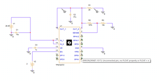
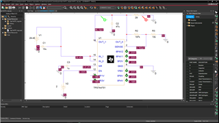
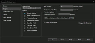
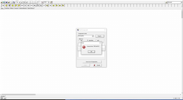
I found SPICE simulation for TPS7A4701 in Pspice and used it to create a simulation model of 29V supply, but I could not get past netlist errors while trying to run transient analysist. The Pspice complained that the ANY-OUT pins are not connected but these pins should be left floating when the feedback resistors are used to set the output voltage. How do I procced?

  • Hi Mark,

    It appears that in the PSpice example project the workaround for this was to add a small wire segment to each any-out pin. This causes PSpice to assign a unique net to that pin, preventing the netlist error.

    Best Regards,

    Alex Davis

  • Hi Alex,

    The workaround you've mentioned did clear netlist errors. Thank you.  The simulation showed the output voltage stuck at zero. My circuit followed the application circuit, but there an error somewhere. Any suggestions?

    Mark


  • Hi Mark,

    This appears to be caused by the way the enable threshold is modeled. An enable input of exactly 2.0V will not enable the device (on the model, anyways). Changing V2 to be even slightly above 2.0V should get the simulation going.

    Best Regards,

    Alex Davis

  • Hi Alex,

    Setting the enable voltage to above 2V did resolve this issue. Thank you.

    When I looked at the TPS7A4701-EP related posts, I have noticed some people are using TPS7A4701-EP with Tina, but when I asked Tina to find TPS7A4701 using 'Find Component' menu command it did not. Is there a trick to it? Does anyone know?

    Mark

  • Hi Alex,

    There is something else the matter with TPS7A4701 Spice model. I built a 28V supply with a pulse generator at Vi that varied the input voltage between 28.45V and 30V. The TPS7A4701 should have regulated such variations out but it did not.

    Mark

  • Hi Mark,

    the TPS7A4701 macromodel might not be included by default in TINA-TI. The .TSM model file provided in SBVM402.ZIP should be able to be added with the Insert > Macro command. 

    It looks like there are a couple of model issues preventing the simulation above from working correctly. Copying your design from above, the model is generating a reference voltage at 1.47V, and overestimating the dropout voltage at ~400mV instead of the 310mV typical specified in the datasheet. The combination of those two means the circuit above tries to regulate to 29.4V, but ends up tracking Vin in dropout instead. 

    I'll need a couple of days to look into whether there's a quick fix for this to improve your sim accuracy, but with the upcoming Memorial Day holiday, it'll likely be next Wednesday before I'll have a chance to look into it in detail. 

    Best Regards,

    Alex Davis

  • Hi Alex,

    I was able to download and insert the TPS7A4701 macromodel into the TINA-TI. The TPS7A4701 model in TINA-TI did not show the issues that it has shown in the 'PSpice for TI'.

    Mark