Tool/software:
Dear TI-Team,
The booster was isolated from my PCB. I powered it directly with a 5 V power supply limited to 1 A. The output is floating. The output MOSFET fails immediately, and I measure a short between SW and GND. I can't understand what happens and what i do wrong. You have some explanations ready?^^
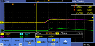
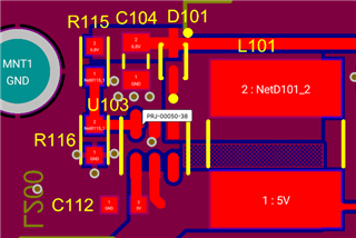
Attached are an oscilloscope screenshot and .csv file showing startup behavior on a booster that initially still works, as well as the PCB layout and schematic. In parallel with the 10 µF output cap, I also added 10 µF and 1 µF MLCCs.
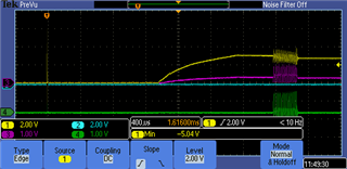
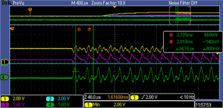
yellow: input should be 5V, only reaches 3.04V. then at the noise, up to 3.68V
purple: feedback 0.8V, only 0.34V. At noise -> up to 1V
Turquoise(blue): stays low
green: current at input. goes into current limit of power supply 1A, while booster is switching. then low again.
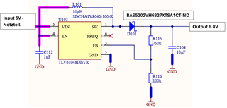
scheamtic:
Thanks for your help in Advance.
best regards
Patrick