This thread has been locked.

If you have a related question, please click the "Ask a related question" button in the top right corner. The newly created question will be automatically linked to this question.

BQ76942: I2C is not communicating if less than 10Kohm Pull-up Resistor used.

Part Number: BQ76942

Tool/software:

Hi,

I am Using the BQ76942 for the 5P4S Lithium -ion Battery pack configuration.

In my architecture the BMS and the battery pack is in separate boards, and We are connecting using the Cable Harness to interface the same.


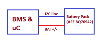
The MCU of the BMS is communicating with Battery Pack of BQ76942 (AFE) over I2C communication. For the Pull-up i have choose the 10K ohm Resistor over 3.3V supply on SCL and SDA.
some how the line capacitance is larger the I2C waveform are have sawtooth like shape. As shown in below image.

Image1 of 10Kohm Pull-up Resistor

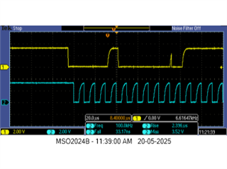
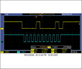
To Improve I have increased the Pull up Value to 4.7Kohm in BMS board, without connecting to Battery Pack (BQ79942 - AFE Board). The Improved waveform overserved.

But once I have connected the Battery Pack (BQ76942 -AFE Board), The SDA line goes pull low and communication is not happening.

Image2 of 4.7 Kohm Pull-up Resistor

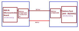
To resolve the above pull-up value related issue and reliable board to board communication, I have used line driver in P82B715DR in both the board.

Not communicating, and pull low the SDA if 1 Kohm Resistor pull up is available.
once remove the 1 K ohm intermediate redriver pull only then start working, but with image1 waveform (Sawtooth like signal).


Image of 10kohm (BMS) - 1 Kohm (Redriver Imtermidiate)  - 10kohm (AFE Board) Pull-up Resistor


Suggest how to improve the reliable communication.

  • Hi Team,

    Support at your earliest convenience. 

    As we are at the stage of product reliability validation and want to escalate the project for production release.

    Thanks & Regards,

    Shashikumar Rai

  • Hi Team,

    Waiting for the response. Please support on the issue.

    Thanks & Regards,

    Shashikumar Rai

  • Hi Shashi,

    Is this still unresolved?  Sorry for the delay responding, the device should be able to accommodate pullups down near 1kOhm, so your 4.7k should be fine.  I wonder if there may be excessive capacitance that isn't recognized, or the gnd connection between the boards has some resistance.

    Thanks,

    Terry

  • Hi Terry,

    Thanks for your reply.

    As I mentioned earlier, the communication doesn't work properly when using pull-up resistors lower than 10kΩ–8kΩ. With such low values, the SDA line is pulled low continuously, preventing communication.

    I suspect this is due to increased line capacitance, as the BMS and Battery Pack (AFE unit) are housed in separate enclosures and connected via a cable — which likely contributes to higher bus capacitance.

    To address this, we have already implemented bus redrivers on both sides of the units to help manage the line capacitance. However, despite using redrivers, the AFE side still does not allow pull-up resistors lower than 10kΩ–8kΩ — using lower values causes the SDA line to remain held low, and the I2C communication remains non-functional.

    Additionally, we've observed that when operating at 100 kHz, the waveform appears sawtooth-shaped, indicating signal integrity issues. Interestingly, reducing the bus speed to 20 kHz improves the waveform. This same behavior has also been observed when using the EVM2400.

    Please let us know your thoughts or recommendations on this.

    Thanks & Regards,
    Shashi Rai

  • Hi Shashi,

    This is odd, we never expect the AFE to clamp the SDA line low continuously, so I'm not sure what would cause that.

    You might put a scope on the I2C bus, but be sure to connect the scope gnd close to the VSS pin of the AFE, the probes close to the SDA and SCL pins of the AFE.  If you do that first while using the 10k pullups, maybe that will provide some hints of what could be happening.  The device can normally handle pullups down close to 1kOhm, so 4.7k is normally fine.

    You can also connect a probe to the gnd line right close to the MCU gnd point, to see if there is any difference between the gnd at the AFE and the gnd at the MCU.  I wonder if maybe something unexpected is causing a gnd shift to occur.

    When using the smaller pullup, I assume when the device first is reset, then SDA and SCL are high, so the device is not clamping SDA.  Then there is maybe an I2C transaction that starts, and somewhere during that transaction the SDA line is held low.  You might try to capture that on the scope, to look closely at the clocks, to see what may have triggered the clamping.

    Thanks,

    Terry