Part Number: LM5146
Other Parts Discussed in Thread: TIDA-01405
Tool/software:
Hello team,
My customer is designing inverting buckboost circuit based on app note "Laying Out an Inverting Buck-boost Converter for Success".
https://www.ti.com/lit/ta/ssztau6/ssztau6.pdf
Question1
My customer is thinking on adding capacitor (CIO) between VIN and -VOUT. (Red drawing)
He thinks that CIO would minimize switching current loop area. (Blue drawing)
Is this theory correct?

Question2
Should customer install cap between VIN and -VOUT?
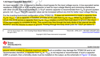
Customer found TIDA-01405 doesn't recommend to add cap betwenn VIN and -VOUT.
https://www.ti.com/lit/ug/tiducv2b/tiducv2b.pdf

However, some App note recommend to use cap between VIN and -VOUT
https://www.ti.com/lit/an/snva856b/snva856b.pdf

Best Regards,
Kei Kuwahara