Other Parts Discussed in Thread: LM5145-Q1
Tool/software:
Dear TI
I designed the circuit 24V to 12V using in LM5146-Q1.
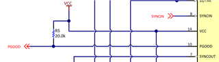
1.VCC Pin connection
In eval board schematic, VCC Pin connect to out(12V).
But in the datasheet, VCC is internal regulator generating at 7.5V.
Does it have any advantage in this connection??
In datasheets, some effecient is better, but I think it's okay to remain NC to VCC.
If VCC doesn't connect to anywhere, is it possible to work wrong or happen serious problem??
2. PGOOD
In eval board schematic, it connect to VCC with pull-up.
If I don't need the PGOOD Function, is it possible to remain NC in PGOOD Pin??
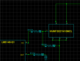
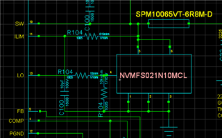
3. added the stable resistor in external MOSFET
In eval board, there is not any resistor around external mosfet.
But about 10ohm Gate resistor helps to avoid rush current or control switching frequency.
And about 10Kohm resistor between Gate and source can disspate electric on gate and prevent boot loss.
I want to make this on the circuit, is it okay to use like below?