This thread has been locked.

If you have a related question, please click the "Ask a related question" button in the top right corner. The newly created question will be automatically linked to this question.

TPS568215: Value of R1 and R2 around EN pin

Part Number: TPS568215

Tool/software:

Hi team,

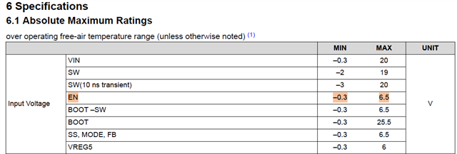
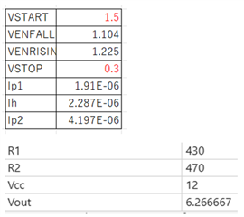
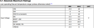
My customer has been considering the value of R1 and R2 around EN pin. He used equation 4 and equation 5 on the datasheet to derive them. When the vaules are below, Vout would be 6.2666 which is very close to the abs max of EN pin which is 6.5V. Are these values correct? or should my customer change the value of R1 and R2?

Best regards,

Shunsuke Yamamoto

  • Hi Yamamoto-san,

    I guess you're asking about the voltage divider on EN pin. It's very straight forward, for Vin=12V; Ven needs to be greater than 1.225 (Venh).

    The recommended value for 12V is R1=57.6k & R2=12.1k as per TPS568215EVM-762 Schematic. 

    Regards,

    Gautam

  • Hi Gautam-san,

    Thank you for the answer. I received the clear question from my customer, and my customer's question is different from what I asked first.

    My customer thinks the equation 4 and equation 5 on the datasheet are incorrect. For example, if R1=57.6k and R2=12.1k, VSTART is 132KV and VSTOP is 6.1V based on the equation 4 and equation 5 on the datasheet. so I think my customer would like to know the correct equations to calculate R1 and R2.

    Best regards,

    Shunsuke Yamamoto

  • Hi Yamamoto-san, 

    My customer thinks the equation 4 and equation 5 on the datasheet are incorrect. For example, if R1=57.6k and R2=12.1k, VSTART is 132KV and VSTOP is 6.1V based on the equation 4 and equation 5 on the datasheet. so I think my customer would like to know the correct equations to calculate R1 and R2.

    The equations are correct. As I calculate, I get Vstart as 6.94V & Vstop as 6.117V with the same equations. Looks like there's some calculation mistake on your end. Please check and let us know.

    Regards,

    Gautam 

  • Hi Gauam-san,

    Thank you for the reply. I have re calculated the equation 4 and equation 5 and found out the calculation was wrong! Thank you for poining it out. My customer also understood that the calculation is wrong.

    In this case, VSTART is 6.94V and VSTOP is 6.117V. VSTART exceeds the abs max of EN pin. Is this design acceptable? 

    Best regards,

    Shunsuke Yamamoto

  • HI Yamamoto-san, 

    These voltages will not directly get applied on EN pin but through the R/1R2 voltage divider. 

    Regards,

    Gautam