This thread has been locked.

If you have a related question, please click the "Ask a related question" button in the top right corner. The newly created question will be automatically linked to this question.

TPS7A4701-EP: Support for dual tracking power supply

Part Number: TPS7A4701-EP
Other Parts Discussed in Thread: OPA992

Tool/software:

Hi,

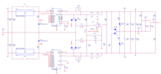
my design is a dual tracking power supply using TPS7A4701, TPS7A3301 and OPA992S.

Attached the simulation and the schematic (BAT54A was corrected with BAT54S).

Simulation seems good but when we measure the output voltages on the pcb we have +4.9V/-5.2V and not +5V/-5V.

When we disassemble the circuit section of the OPA and close JP2 and JP4 the voltages balance each other at +5V/-5V.

What could be the problem?

Thanks for your support.

2818.Dual Tracking Power Supply.TSC

  • Hi HD,

    Can you measure voltages at the inverting and noninverting inputs of the OPA992, as well as its output? If it's possible to measure input current into each LDO, that would be useful to know as well.

    Best Regards,

    Alex Davis

  • Hi Alex,

    non-inverting input is -15mV

    inverting input is +28mV

    output is +57mV

    It is not working because the configuration is non-inverting with gain 2, so the output should be negative. The feedback loop is not working.

    When the op-amp circuit is not present, the LDOs give symmetrical output voltages +5.08V/-4.99V, when we mount the op-amp circuit the symmetry is ruined and the voltages become unbalanced towards the negative voltage.

    At the moment we are unable to measure the input currents to the LDOs.

    We tried also to use 0.1% resistor for 10K and 100K.

    Best Regards.

    HD

  • Hi HD,

    That is strange. Is that reproducible with multiple OPA992s? With the resistor values listed, I wouldn't expect there to be any issues with output current on the op amp that'd cause that behavior. 

    Have you measured the op amp output with an oscilloscope? Is it possible that there's a stability issue that's showing up as a DC offset? 

    Best Regards,

    Alex Davis

  • Hi Alex,

    we tried it on 3 boards but the result is the same. It is strange because the simulation seems to work.

    Attached a scopepicture about the output of OPA992S.

    Let me know.

    Best Regards,

    HD

  • Hi HD,

    That oscillation makes me wonder if there's a characteristic of the LDOs that's not captured in the SPICE models. The TPS7A3301 model in particular seems to be very basic and may not fully depict the behavior of the actual device.

    Unfortunately, a full stability analysis isn't doable with the models we have right now. As a first step, I'd try increasing C306 to 100nF.

    Best Regards,

    Alex Davis

  • Hi Alex,

    I tried to increasing C306 to 100nF but nothing changes.

    We tried also to decrease R268 to105K-106K and to reduce the gain decreasing R272 to 47K but nothing...

    There must be something that does not allow the OPA to regulate well.

    Best Regards,

    HD

  • Hi HD,

    Is there a minimum load that's present on the LDO outputs during startup? If both LDOs are lightly loaded, I wonder if this oscillation could be due to the LDO outputs not being able to sink current and regulate voltage down if they overshoot. If so, adding an additional bleeder resistor across the output could help. 

    If that doesn't help, I had a couple of questions. First, can you help me understand what is driving the requirement for the symmetric ramp and balanced supplies? Would it be possible to still meet this requirement without the op amp circuit? 

    Second, while I'm hesitant to suggest adding more components and complexity to your design, could one of our tracking LDOs work as a substitute for the positive supply? In that case, the op amp could be reconfigured as an inverting gain of 1 from the negative LDO to drive the tracking pin, and both outputs would track symmetrically. Another possibility would be the TPS7A39. In either case, I realize that multiple devices would be required to meet the 1A output capability of your current solution, which probably rules these out as options. 

    Best Regards,

    Alex Davis

  • Hi Alex,

    there are about 20 op-amps (+5/-5V dual supply) as load.

    Oscillation is no longer present with C306=100nF, but the output voltages remain +4.94V/-5.2V.
    We also tried to lower the op amp gain from 2 to 1.3 without results. We also lowered the resistors from 107K and 102K to 47K obviously maintaining the ratios with the higher resistors, i.e. the 274K became 120K and the 332K became 153K but without results. We did this thinking about the fact that the op amp is unable to close the loop and therefore by lowering the resistors from 107K and 102K we could favor its feedback. In fact it is strange that being a non-inverting, it has a negative value at the input and a positive value at the output. Probably we need to further lower these values ​​of the lower resistors?
    The reason for choosing balanced voltages is only to have the op amps always powered symmetrically during startup... but currently it wouldn't be essential... it's more of a test circuit for the future, to start seeing a solution... so for now we could even leave the section with the op amp unmounted... but we wouldn't solve the problem because then we would really need a dual tracking circuit +5/-5V 1A... and it's strange that we can't get to the bottom of it since it's not a complex circuit.
    So for the moment we can't afford to make complicated changes to the architecture by introducing new components because we don't have time to make a new layout.
    I'll also send you a link from where we took inspiration for the proposed solution:


    https://www.eetimes.com/use-a-tracking-power-supply-to-improve-signal-chain-performance/


    I don't understand what you mean when you say: "could one of our tracking LDOs work as a substitute for the positive supply? In that case, the op amp could be reconfigured as an inverting gain of 1 from the negative LDO to drive the tracking pin, and both outputs would track symmetrically".

    Best Regards,

    HD

  • Hi HD,

    To clarify my last suggestion, we have a few LDO devices that can accept an external voltage reference which they will then track. They're used more commonly to power ratiometric sensors off-board in automotive applications, but the tracking behavior could be applied here. Using the exsting negative LDO plus an G=-1 op amp to provide the reference to the tracker. I realize that's not a viable solution given the constraints in your design, however. 

    Looking over the EETimes article and circuit, I have one other possibility to try. It looks like they're using lower-valued resistors in the dividers for both LDOs. If possible, can you reduce the resistor values by 1 decade and retest (e.g. 274kΩ  -> 27.4kΩ)? My thinking here is that the large resistor values combined with the feedforward capacitance on the LDO outputs may be contributing to the instability you're seeing.

    Best Regards,

    Alex Davis

  • Hi HD,

    I wanted to check in on this. Were you able to resolve the issue? 

    Best Regards,

    Alex Davis

  • Hi Alex,

    we resolved the issue using 10K resistors for R268 and R275, 28.6K for R263, 30K for R279 and 100nF for C306.

    Now the output voltages are very close to +/-5V.

    Thanks for your support.

    Best Regards,

    HD

  • Hi HD,

    Glad that solved the problem! I'll flag this thread as resolved, but feel free to re-open it if you need. 

    Best Regards,

    Alex Davis